Blog

  • Travel Speed Limiting Systems for EOT Cranes: Enhancing Safety and Efficiency

    Electric Overhead Traveling (EOT) cranes are essential pieces of equipment in manufacturing, construction, warehousing, and material handling industries. Their ability to lift and transport heavy loads across a facility with precision makes them indispensable. However, operating these cranes safely and efficiently requires sophisticated control and safety systems. Among these, travel speed limiting systems play a crucial role in ensuring operational safety, protecting equipment, and improving workflow efficiency.

    EOT crane

    Understanding Travel Speed in EOT Cranes

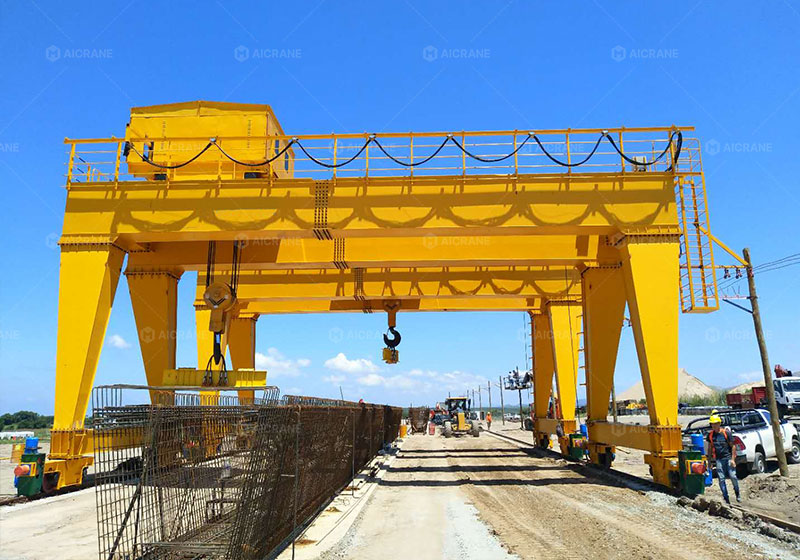
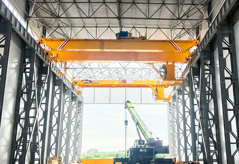
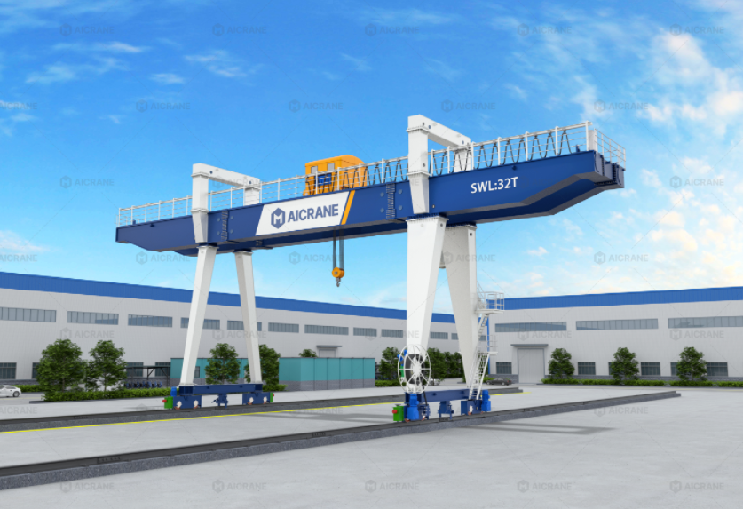
    Travel speed in an EOT crane for sale refers to the velocity at which the crane moves along its runway or tracks. This includes both the main girder movement (trolley movement along the crane bridge) and the bridge movement itself (crane movement along the runway rails). EOT cranes typically have variable speed controls to allow operators to adjust speed according to load, working conditions, and environmental factors.

    While higher travel speeds can improve operational efficiency, excessive speed poses significant risks. Fast crane movement increases the likelihood of load sway, collisions, and operator errors. It also places additional stress on mechanical and structural components, potentially shortening equipment lifespan. To mitigate these risks, engineers implement travel speed limiting systems.

    What Are Travel Speed Limiting Systems?

    A travel speed limiting system is a safety and control mechanism integrated into an EOT crane to restrict the crane’s maximum allowable speed during operation. These systems are designed to prevent the crane from exceeding safe operating speeds under various conditions, reducing the likelihood of accidents and mechanical damage.

    Modern travel speed limiting systems can be electronic, mechanical, or a combination of both, and they often integrate with the crane’s variable frequency drives (VFDs), programmable logic controllers (PLCs), and other automation systems.

    Key Objectives of Travel Speed Limiting Systems

    1. Operator Safety: Prevents accidents caused by excessive crane speed or sudden movements.

    2. Load Stability: Minimizes load swing by controlling acceleration and deceleration.

    3. Equipment Protection: Reduces wear and tear on motors, gearboxes, brakes, wheels, and rails.

    4. Compliance: Ensures the crane adheres to national and international safety standards.

    5. Operational Efficiency: Maintains smooth operation without unnecessary slowdowns in safe conditions.

    Components of a Travel Speed Limiting System

    Travel speed limiting systems are composed of several integrated components that work together to monitor and control crane movement:

    1. Sensors and Encoders

    Sensors detect the crane’s actual speed along the rails or runway. Encoders on motors measure the rotational speed, which is then translated into linear travel speed. These sensors continuously feed data to the control system, allowing real-time speed monitoring.

    2. Programmable Logic Controller (PLC)

    The PLC acts as the brain of the system. It receives input from sensors, compares the measured speed with pre-set speed limits, and sends control signals to the drive system to adjust the speed accordingly.

    3. Variable Frequency Drive (VFD) Integration

    Most modern EOT cranes are equipped with VFDs to allow smooth and precise speed control. When the PLC detects that the crane is approaching or exceeding the maximum safe speed, it signals the VFD to reduce power to the motors, thus slowing the crane down.

    4. Mechanical Speed Limiters

    In some cranes, particularly older models, mechanical speed limiters such as centrifugal governors or geared limiters are used. These devices physically restrict the maximum speed of the crane trolley or bridge, offering a failsafe if electronic systems fail.

    5. Operator Interface

    Crane operators need clear feedback about the speed limits. Control panels or HMI (Human Machine Interface) screens display current speed, set limits, and alerts, allowing operators to make informed decisions during operation.

    overhead EOT crane

    Types of Travel Speed Limiting Systems

    Travel speed limiting systems can vary depending on the crane design, application, and manufacturer. The main types include:

    1. Fixed Speed Limiting

    The crane is restricted to a pre-determined maximum speed, regardless of load or working conditions. This simple system is suitable for operations with uniform load sizes and minimal dynamic risk factors.

    2. Load-Dependent Speed Limiting

    In this system, the crane’s maximum travel speed changes according to the weight of the load. Heavier loads require slower speeds to reduce load sway and stress on the crane structure. Sensors measure the load weight, and the control system automatically adjusts travel speed.

    3. Zone-Based Speed Limiting

    Some facilities divide the crane runway into zones. Certain zones—such as areas near personnel, sensitive equipment, or tight corners—require reduced travel speed. The crane automatically adjusts its speed based on its current zone, enhancing safety in high-risk areas.

    4. Dynamic Adaptive Speed Control

    Advanced EOT cranes use real-time adaptive control algorithms to optimize speed based on multiple factors, including load, crane condition, wind speed (in outdoor facilities), and operator commands. This type of system provides the highest level of safety and efficiency but requires sophisticated electronics and software.

    Benefits of Travel Speed Limiting Systems

    Integrating travel speed limiting systems into EOT cranes brings multiple benefits for both operators and facility managers:

    1. Enhanced Safety

    Speed control directly reduces the risk of accidents. Limiting travel speed prevents collisions with structures or personnel, reduces load swing, and minimizes sudden movements that could destabilize loads.

    2. Increased Equipment Longevity

    By controlling acceleration, deceleration, and maximum speed, these systems reduce mechanical stress on motors, brakes, and structural components. This prolongs service life and reduces maintenance costs.

    3. Improved Load Handling

    Maintaining optimal travel speed ensures smoother operation. Controlled movement reduces the risk of damaging delicate or heavy loads, which is crucial for industries like manufacturing, warehousing, and material processing.

    4. Regulatory Compliance

    Many countries mandate speed control measures for cranes under national safety standards (e.g., OSHA in the United States, DGUV in Germany, ISO 9927). Implementing speed limiting systems helps companies meet legal requirements.

    5. Operational Efficiency

    While it may seem counterintuitive, speed limiting systems can improve overall efficiency. By preventing unsafe high-speed movements, they reduce downtime caused by accidents or load mishandling. Operators can also work more confidently, knowing the crane is operating within safe parameters.

    Installation and Maintenance Considerations

    Proper installation and regular maintenance of travel speed limiting systems are essential to ensure reliability:

    1. Calibration
      Sensors and controllers must be accurately calibrated to ensure that speed measurements and limits are precise.

    2. Testing
      After installation, the system should undergo comprehensive testing under various loads and operating conditions to verify correct functionality.

    3. Routine Inspections
      Periodic inspections of sensors, VFDs, mechanical limiters, and wiring ensure consistent performance and prevent failures.

    4. Software Updates
      For electronic systems, software updates may be required to address bugs, improve algorithms, or integrate new operational features.

    5. Operator Training
      Operators should be trained to understand speed limiting functions, warning signals, and emergency procedures.

    Real-World Applications

    Travel speed limiting systems are widely used across industries:

    • Steel and Aluminum Mills: Heavy duty overhead cranes handle molten metal and large coils. Speed limiting ensures safe transport without destabilizing heavy loads.

    • Automotive Manufacturing: Cranes move car bodies or assembly components, requiring precise speed control to avoid damage.

    • Warehousing and Logistics: Automated or semi-automated crane systems benefit from zone-based speed control, especially near personnel or storage racks.

    • Shipbuilding and Marine Industry: Cranes lift large ship components and equipment, where load swing could have catastrophic consequences if speeds are uncontrolled.

    Future Trends

    With advancements in automation and Industry 4.0, travel speed limiting systems are becoming more intelligent and integrated:

    • Predictive Algorithms: Using AI and machine learning, cranes can anticipate unsafe conditions and adjust speed proactively.

    • IoT Connectivity: Speed data can be transmitted to facility management systems for real-time monitoring and predictive maintenance.

    • Integration with Anti-Sway Systems: Combined speed and anti-sway controls allow cranes to move heavy loads faster without compromising stability.

    Conclusion

    Travel speed limiting systems are critical for safe, efficient, and reliable EOT crane operations. They protect operators, prevent equipment damage, and ensure compliance with safety standards while optimizing operational efficiency. By carefully selecting and maintaining these systems, businesses can maximize the performance of their cranes, reduce downtime, and protect both their workforce and valuable materials.

    As crane technology evolves, travel speed limiting systems will become increasingly sophisticated, integrating predictive analytics, IoT monitoring, and adaptive controls, further enhancing safety and efficiency across all industries that rely on EOT cranes.

  • Environmental Considerations for Boat Gantry Cranes in Coastal Areas

    Boat gantry cranes — such as boat hoists, RTG-style marine gantries, and wheel-mounted boat lifting systems — play a vital role in maritime industries. They handle tasks like launching and retrieving boats, performing maintenance, lifting large vessels during repair, and facilitating dry-dock operations. In coastal areas, however, their operation intersects directly with delicate marine ecosystems, sensitive shorelines, and climatic challenges. As such, engineers, operators, and marine facility planners must consider environmental impacts when selecting, installing, and operating these cranes.

    This article explores the key environmental factors associated with boat gantry cranes in coastal environments and outlines best practices for reducing negative impacts while maintaining efficient, safe lifting operations.

    boat gantry crane

    1. Understanding Coastal Environmental Sensitivities

    1.1 Marine Ecosystems and Habitat Protection

    Coastal regions often contain essential habitats such as estuaries, coral reefs, seagrass beds, and tidal marshes. These areas support biodiversity and serve as nurseries for fish and other marine life.

    A boat gantry crane’s operation — including fuel handling, hydraulic systems, and mechanical movements — comes with risks of leaks, spills, and particulate contamination. Even small amounts of contaminants released into coastal waters can harm fragile organisms, alter food chains, and degrade water quality.

    1.2 Sediment and Shoreline Stability

    Coastal soil structures are often loose, sandy, or highly organic, meaning they are susceptible to erosion and disturbance. Heavy equipment like gantry cranes can compact soil, disrupt natural tidal flows, and contribute to shoreline instability.

    1.3 Air and Noise Pollution

    Coastal facilities may be close to residential communities and tourist areas. Emissions from diesel engines, hydraulic equipment, and noise from crane operations can affect both human and wildlife well-being — particularly sensitive species like shorebirds, seals, and nesting turtles.

    2. Environmental Impacts of Boat Gantry Cranes

    2.1 Emissions and Air Quality Concerns

    Traditional boat gantry cranes operate on diesel or gas power, which produces greenhouse gases (GHGs), particulate matter, and nitrogen oxides (NOx). In regions with strict air quality regulations, this contributes to non-attainment zones and limits permissible equipment emissions.

    Environmental risk: Persistent emissions can degrade regional air quality, contribute to health issues in nearby communities, and accelerate acidification in coastal waters.

    Best practice: Consider electric or hybrid power systems for gantry cranes, especially for marinas and repair yards that operate frequently or near populated coastal zones.

    2.2 Soil and Water Contamination

    Hydraulic fluids, lubricants, and fuels are common in crane systems. Leaks or spills can enter soil or surface water, particularly in low-lying coastal facilities that are vulnerable to flooding and tidal influence.

    Environmental risk: Petroleum hydrocarbons and synthetic fluids can poison aquatic life, smother benthic habitats, and disrupt biochemical cycles in sediments.

    Best practice: Implement secondary containment, spill response plans, and use biodegradable hydraulic fluids where possible to minimize contamination risks.

    2.3 Noise and Visual Disturbance

    Operational noises from engines, chain and wire rope movement, and load handling affect both wildlife and human populations. Especially in ecologically sensitive areas, noise pollution can alter animal behaviors — like feeding, migration, and breeding patterns.

    Visual impacts from large gantry structures may also disrupt scenic coastal landscapes, affecting tourism and local aesthetics.

    Best practice: Use noise mitigation strategies such as acoustic enclosures, schedule operations outside wildlife breeding seasons, and consider crane designs that minimize visual intrusion.

    2.4 Disruption of Marine Transportation and Fishing

    Boat gantry crane operations can interfere with local vessel traffic if poorly planned. Float lines, staging areas, and movements of large loads can restrict navigation channels and collide with fishing operations.

    Environmental risk: Increased entanglement hazards for fishing gear, vessel collisions, and delays that lead to congestion and additional fuel burn in harbor areas.

    Best practice: Designate clear work zones, coordinate with harbor masters, and integrate traffic management systems to reduce interference with marine traffic and fishing activities.

    boat lift crane

    3. Design Solutions to Minimize Environmental Impact

    3.1 Electrification and Alternative Power Sources

    Electric gantry cranes produce zero on-site emissions, reduce fuel storage risks, and are quiet compared to diesel engines. In coastal areas with grid access, electric power dramatically lowers the environmental footprint of lifting operations.

    Solar or wind hybrid systems can further improve sustainability in remote coastal regions or where grid reliability is limited.

    3.2 Corrosion-Resistant Materials

    Saltwater and sea breeze create a highly corrosive environment. Corrosion accelerates mechanical degradation, increases maintenance cycles, and raises the likelihood of leaks.

    Using corrosion-resistant metals (e.g., stainless steels, specialized alloys), high-grade coatings, and sealed electrical components improves longevity and reduces waste from frequent repairs.

    3.3 Biodegradable Hydraulic Fluids

    Replacing petroleum-based hydraulic oils with biodegradable alternatives reduces the environmental hazard from leaks and accidental spills. While these fluids may have slightly different performance characteristics, many modern biodegradable options meet or exceed operational standards.

    3.4 On-Site Water and Sediment Filtration

    Stormwater and washdown water from boat lift crane areas can carry oils, metals, and particulates into coastal waters. Installing filtration systems, oil/water separators, and sediment traps prevents pollutants from entering natural water bodies.

    4. Operational Practices for Environmental Protection

    4.1 Spill Prevention and Response Planning

    Even with good design, spillage or leakage events can occur. A comprehensive spill prevention, control, and countermeasure (SPCC) plan is essential.

    Elements should include:

    • Regular inspections of fuel and fluid systems

    • Clearly labeled containment areas

    • Spill kits and absorbent materials on site

    • Staff trained in emergency response

    4.2 Scheduled Maintenance and Monitoring

    Routine maintenance keeps gantry cranes operating efficiently and reduces the risk of catastrophic failures. Regular checks of hydraulic hoses, seals, and electrical systems identify issues before they become environmental hazards.

    Documentation and monitoring also help demonstrate compliance with regulatory requirements.

    4.3 Environmental Regulatory Compliance

    Coastal marine operations are often subject to regulations from agencies such as:

    • U.S. Environmental Protection Agency (EPA)

    • U.S. Army Corps of Engineers

    • State coastal commissions

    • Local marina and harbor authorities

    Permits, reporting requirements, and environmental impact assessments may be mandatory before installation or expansion of crane operations. Engaging with regulators early ensures smoother approvals and mitigates future compliance issues.

    5. Community and Stakeholder Engagement

    5.1 Working with Local Fishermen and Businesses

    Coastal communities depend on fishing, tourism, and recreation. Engaging stakeholders in planning and operations fosters goodwill and prevents conflicts. Regular communication about planned crane activities, restricted zones, and operational schedules reduces surprises and enhances cooperation.

    5.2 Transparent Environmental Reporting

    Publicly sharing environmental performance — such as emission reductions, spill incidents, and mitigation measures — builds trust with regulators and local residents. Some facilities participate in voluntary environmental certification programs, which can further boost reputation and assure the community of responsible operations.

    6. Case Examples and Lessons Learned

    While not exhaustive, several high-profile marine facilities have successfully implemented environmental best practices for boat gantry cranes:

    • Electric Boat Hoist Implementation: Marine yards that converted from diesel to electric gantry systems saw dramatic reductions in noise and emissions — particularly beneficial in densely populated coastal cities.

    • Stormwater Capture Systems: Facilities that installed full filtration systems for washdown and runoff eliminated direct discharge of contaminated water into sailing channels.

    • Community Environmental Partnerships: Some harbors partnered with local conservation organizations to monitor water quality and adapt operational practices based on seasonal wildlife patterns.

    Conclusion

    Boat gantry cranes in coastal areas enable critical marine activities — but they must be managed with environmental stewardship in mind. From emissions and pollution risks to impacts on wildlife and shoreline integrity, planners and operators face unique challenges in coastal environments.

    By incorporating eco-friendly equipment design, using alternative power sources, planning for spill prevention, and engaging stakeholders in ongoing dialogue, facilities can significantly reduce environmental impacts. Ultimately, sustainable gantry crane operations not only protect fragile coastal ecosystems but also ensure long-term operational viability, regulatory compliance, and positive community relationships.

  • Power Supply Stability Considerations for Container Lifting Crane Operation

    Container lifting cranes are essential equipment in modern ports, logistics centers, and container terminals. These cranes, including Rubber Tyred Gantry (RTG) cranes, Rail Mounted Gantry (RMG) cranes, and ship-to-shore (STS) container cranes, are designed to handle massive loads efficiently and safely. One often overlooked but critical factor in their operation is the stability of the power supply. Power supply fluctuations, interruptions, or instability can significantly impact crane performance, operational safety, and long-term equipment reliability. Understanding the power requirements, potential risks, and best practices for stable energy supply is essential for operators and facility managers alike.

    container gantry crane

    The Importance of Stable Power Supply in Container Lifting Operations

    Container lifting cranes rely heavily on electric power to drive multiple systems, including hoists, trolleys, cranes’ movement along rails or wheels, braking systems, and auxiliary equipment such as lighting, control systems, and safety devices. A stable power supply ensures that these systems operate smoothly and efficiently.

    Operational Efficiency

    Unstable power can lead to sudden speed variations in container lifting crane movements. For example, voltage drops may reduce hoist speed, delaying container handling operations, while sudden voltage spikes can accelerate motion unexpectedly, compromising precision in container placement. Smooth and consistent power delivery ensures that cranes can handle containers at optimal speeds while maintaining accuracy, improving overall throughput at terminals.

    Safety Considerations

    Container cranes handle extremely heavy loads, often exceeding 40 tons per container. Power instability increases the risk of accidents. Voltage fluctuations can cause hoist motors to stall, braking systems to underperform, or control electronics to malfunction. Any of these scenarios can lead to dropped containers, collisions, or injuries to operators and ground staff. Ensuring stable power supply is therefore not only a matter of operational efficiency but also of workplace safety.

    Equipment Longevity

    Frequent power fluctuations can also affect the lifespan of a crane’s components. Motors, frequency converters, and control systems are particularly sensitive to voltage irregularities. High-voltage spikes may cause insulation failure, while low-voltage conditions can lead to overheating of motors and wear on mechanical systems. Over time, these stresses increase maintenance costs and reduce overall equipment reliability.

    Types of Power Supply Issues Affecting Crane Operations

    Container lifting cranes can be impacted by a variety of power supply issues. Understanding these issues is the first step toward designing a robust power management system.

    Voltage Fluctuations

    Voltage fluctuations occur when the supplied voltage deviates from the nominal value. These deviations can be caused by grid instability, large simultaneous loads in the facility, or upstream electrical disturbances. Fluctuations can lead to inconsistent crane speed, erratic movement, and operational delays.

    Power Outages

    Temporary or prolonged power outages are particularly disruptive. Even a short interruption can halt crane operations, leaving containers suspended or partially moved. This can create unsafe working conditions and lead to scheduling disruptions across the terminal.

    Harmonics and Electrical Noise

    Modern cranes often use variable frequency drives (VFDs) and advanced electronics. These systems are sensitive to harmonics and electrical noise, which can result from industrial equipment, nearby transformers, or improper grounding. Electrical noise can trigger false alarms, cause control errors, or damage sensitive electronics over time.

    Phase Imbalance

    Three-phase power is standard for high-capacity cranes. Any imbalance in phase voltage can cause motors to operate inefficiently, generate excessive heat, or trigger protection systems to shut down the crane. Monitoring and correcting phase imbalances is essential for stable crane operation.

    container lifting crane

    Ensuring Stable Power Supply for Container Cranes

    Given the potential risks, several measures can be taken to ensure stable power supply and reliable crane operation.

    Dedicated Power Lines

    Crane operations should ideally have dedicated power lines separate from other facility loads. This reduces the impact of large transient loads from lighting systems, forklifts, or other industrial equipment that may cause voltage dips or surges.

    Voltage Regulation and Uninterruptible Power Supplies (UPS)

    Voltage regulators or stabilizers maintain voltage within safe operating limits, preventing damage to motors and control systems. In addition, UPS systems can provide backup power during brief outages, allowing operators to safely lower suspended containers and maintain operational continuity.

    Surge Protection and Lightning Arrestors

    Installing surge protection devices and lightning arrestors helps mitigate the impact of sudden voltage spikes caused by electrical storms or switching operations on the grid. This is critical for protecting sensitive electronic components and avoiding operational interruptions.

    Energy Storage and Hybrid Systems

    Some modern container terminals use hybrid RTG cranes equipped with onboard energy storage systems such as batteries or supercapacitors. These systems provide consistent power to the crane, reduce dependency on unstable grid supply, and can even store regenerative energy during braking. Hybrid cranes are particularly effective in areas with frequent power fluctuations or weak grid infrastructure.

    Routine Power Quality Monitoring

    Regular monitoring of voltage, current, harmonics, and phase balance is crucial for proactive maintenance. Power quality analyzers can detect anomalies before they lead to equipment failure, allowing maintenance teams to address issues such as phase imbalance, harmonic distortion, or voltage sags in advance.

    Redundant Power Supply

    For critical terminals where crane operation cannot be interrupted, redundant power supply lines from separate feeders can provide backup in case of primary line failure. This redundancy ensures continuous operation and prevents downtime due to electrical failures.

    Design Considerations for Power-Stable Cranes

    Manufacturers of container lifting cranes also incorporate power stability considerations into gantry crane design:

    • Variable Frequency Drives (VFDs): Modern cranes use VFDs to control hoist and trolley motors. VFDs can adapt to minor voltage fluctuations, ensuring consistent speed and torque.

    • Energy Recovery Systems: Regenerative braking systems convert kinetic energy during lowering operations back into electrical energy, smoothing power demands on the grid.

    • Intelligent Control Systems: Advanced control software can detect power irregularities and adjust operational parameters in real-time, preventing overloads or motor stalling.

    • Insulated and Robust Electrical Components: Motors and transformers are designed with insulation classes that can tolerate voltage fluctuations, high temperatures, and harmonics without premature degradation.

    Operational Best Practices

    In addition to technical solutions, operational practices are essential for managing power stability:

    • Load Scheduling: Avoid simultaneous operation of multiple cranes at full capacity, which can overload the electrical supply and cause voltage dips.

    • Regular Maintenance: Ensure that electrical connections, transformers, and contactors are inspected and maintained to prevent resistive losses or intermittent faults.

    • Operator Training: Operators should be trained to recognize signs of power instability, such as jerky motion, unusual noises, or abnormal braking behavior.

    • Emergency Procedures: Clearly defined protocols for power loss scenarios, including safe lowering of containers, reduce the risk of accidents during sudden outages.

    Conclusion

    Power supply stability is a critical factor in the operation of container lifting cranes. Voltage fluctuations, power outages, phase imbalances, and electrical noise can all impact operational efficiency, safety, and equipment lifespan. Addressing these issues requires a combination of technical solutions—including dedicated power lines, voltage regulation, surge protection, energy storage, and intelligent control systems—as well as operational best practices such as proper load scheduling, routine maintenance, and operator training.

    Terminals that invest in stable and reliable power infrastructure can achieve higher crane productivity, reduce maintenance costs, and ensure the safety of personnel and cargo. As container traffic continues to grow globally, power stability will remain a cornerstone of efficient, safe, and sustainable crane operations.

  • How Increasing Capacity Affects Double Girder Gantry Crane Steel Structure

    As industrial lifting demands continue to grow, many projects require double girder gantry cranes with increasingly higher lifting capacities. From 20 tons to 100 tons and beyond, capacity upgrades are not simply a matter of installing a larger hoist. Increasing the rated load of a double girder gantry crane has far-reaching structural implications, particularly for the steel structure that forms the backbone of the crane system.

    Understanding how increased capacity affects the steel structure is critical for crane designers, manufacturers, project engineers, and end users. Improper structural scaling can lead to excessive deflection, fatigue damage, reduced service life, or even structural failure. This article explores in detail how increasing lifting capacity influences the steel structure of double girder gantry cranes, including girder design, leg systems, connections, materials, and compliance with international standards.

    double girder gantry crane

    1. Relationship Between Lifting Capacity and Structural Load

    1.1 Direct Increase in Static Load

    The most obvious impact of higher lifting capacity is the increase in static vertical load acting on the crane structure. When capacity doubles, the steel structure must support not only the additional lifted weight but also:

    • Heavier hoisting mechanisms

    • Larger trolley assemblies

    • Stronger rails and walkways

    This means that the total design load grows disproportionately, not linearly. For example, upgrading a crane from 50 tons to 100 tons may increase the total structural load by more than 100% once self-weight and auxiliary equipment are included.

    1.2 Amplification of Dynamic Loads

    Higher capacity cranes experience stronger dynamic effects, including:

    • Impact loads during lifting and lowering

    • Inertia forces during trolley travel

    • Braking and acceleration forces

    These dynamic loads significantly affect stress distribution in the steel structure, particularly at mid-span girders, wheel loads, and leg-to-girder connections.

    2. Impact on Main Girder Design

    2.1 Girder Section Size and Shape

    As capacity increases, the main girders must resist higher bending moments and shear forces. This directly influences:

    • Girder height (depth)

    • Web plate thickness

    • Flange plate width and thickness

    In high-capacity double girder gantry cranes, box-type girders are commonly used because they offer:

    • Higher torsional rigidity

    • Better fatigue performance

    • Improved resistance to lateral deformation

    Increasing capacity often requires significantly deeper girders, not just thicker plates, to control deflection within allowable limits.

    2.2 Deflection Control Requirements

    Structural deflection becomes more critical as capacity increases. Excessive deflection can:

    • Affect trolley movement stability

    • Cause uneven wheel loads

    • Reduce operator comfort and safety

    Typical deflection limits (such as L/700 or L/800) become more difficult to achieve at higher capacities, forcing designers to optimize girder geometry and material distribution.

    3. Effects on Gantry Legs and Support System

    3.1 Leg Section Reinforcement

    The gantry legs transmit all vertical and horizontal forces to the foundation. As lifting capacity increases:

    • Axial compression forces rise sharply

    • Bending moments from wind and trolley movement increase

    • Buckling risk becomes a primary concern

    High-capacity cranes often require box-type or multi-plate welded legs, replacing simpler I-beam or tubular designs used in lower-capacity systems.

    3.2 Stiffness and Lateral Stability

    Larger loads demand greater lateral stiffness to resist:

    • Skewing forces during travel

    • Wind loads in outdoor applications

    • Uneven rail conditions

    This leads to wider leg spacing, thicker plates, and additional internal stiffeners within the leg structure.

    double beam gantry crane

    4. Influence on Connection and Joint Design

    4.1 Bolted vs. Welded Connections

    With increased capacity, joint design becomes more critical. High-stress regions such as:

    • Girder-to-leg connections

    • End beam interfaces

    • Diagonal bracing joints

    must withstand greater cyclic loads. As a result:

    • High-strength bolts (e.g., Grade 10.9) are often required

    • Weld sizes and inspection standards increase

    • Stress concentration must be carefully managed

    4.2 Fatigue Performance of Joints

    Higher capacity cranes often operate under heavy-duty classifications (A5, A6, A7), increasing fatigue risk. Structural joints must be designed to:

    • Minimize stress concentrations

    • Use smooth load transitions

    • Meet fatigue design criteria under international standards

    5. Material Selection and Steel Grade Upgrades

    5.1 Higher Strength Steel Requirements

    To control weight while increasing capacity, designers often upgrade steel grades, such as:

    • From Q235 to Q345 or Q355

    • From S235 to S355 or S460

    Higher-strength steel allows thinner sections while maintaining load-bearing capacity, but it also requires:

    • Stricter welding procedures

    • Better quality control

    • Enhanced inspection methods

    5.2 Trade-Off Between Strength and Toughness

    In heavy-duty and cold-environment applications, higher capacity large gantry cranes must balance strength with toughness. Brittle fracture risk increases if inappropriate steel grades are used, making material selection a critical structural consideration.

    6. Effects on Wheel Loads and End Beams

    6.1 Increased Wheel Pressure

    Higher lifting capacity significantly increases wheel loads, which affects:

    • End beam structural design

    • Rail selection

    • Wheel material and diameter

    The steel structure must distribute wheel loads evenly to prevent local overstressing and premature rail damage.

    6.2 Reinforcement of End Beams

    End beams may require:

    • Thicker web plates

    • Reinforced wheel seats

    • Additional diaphragms

    to accommodate the higher reaction forces transferred from the main girders.

    7. Influence on Bracing and Overall Structural Stiffness

    7.1 Need for Additional Bracing

    As capacity increases, structural stiffness becomes more important than pure strength. Designers often add:

    • Horizontal bracing between girders

    • Diagonal bracing in leg systems

    • Portal frame reinforcements

    These elements help control deformation and improve overall structural integrity.

    7.2 Resistance to Environmental Loads

    High-capacity gantry cranes are frequently installed outdoors, where wind loads combine with high lifting loads. A stronger steel structure ensures:

    • Better resistance to overturning moments

    • Improved stability during non-operational conditions

    8. Impact on Manufacturing and Fabrication Process

    8.1 Increased Welding Volume

    Higher capacity steel structures require:

    • Thicker plates

    • Longer weld seams

    • Multi-pass welding

    This increases fabrication complexity and demands higher welding quality standards.

    8.2 Stricter Quality Control

    Non-destructive testing (NDT), such as ultrasonic testing (UT) and magnetic particle testing (MT), becomes more critical as structural stresses increase. Fabrication tolerances must be tightly controlled to ensure structural performance.

    9. Compliance with Standards and Safety Margins

    Increasing capacity means the steel structure must comply with stricter requirements under standards such as:

    • FEM

    • ISO

    • EN

    • CMAA

    Safety factors, fatigue classifications, and load combinations all become more conservative, directly influencing structural dimensions and material usage.

    10. Economic and Operational Implications

    10.1 Cost Increase Is Not Linear

    Increasing crane capacity significantly affects steel structure cost due to:

    • Heavier materials

    • Higher steel grades

    • Increased fabrication time

    However, a well-optimized structure can minimize unnecessary weight while ensuring safety.

    10.2 Long-Term Performance Benefits

    A properly designed high-capacity steel structure delivers:

    • Longer service life

    • Reduced maintenance

    • Higher operational reliability

    These benefits often outweigh the higher initial investment.

    Conclusion

    Increasing the lifting capacity of a double girder gantry crane has a profound impact on its steel structure. From main girders and legs to connections, materials, and fabrication processes, every structural element must be carefully redesigned to handle higher static and dynamic loads.

    Rather than simple scaling, capacity increases require holistic structural optimization, balancing strength, stiffness, fatigue resistance, and economic efficiency. For high-capacity gantry cranes, the steel structure is not just a supporting frame—it is a critical engineered system that determines safety, performance, and long-term value.

    Understanding these structural implications allows project owners and engineers to make informed decisions, ensuring that higher capacity gantry cranes operate safely, efficiently, and reliably throughout their service life.

  • Rubber Tyred Gantry Crane Technology for Wind Power & Heavy Equipment

    The rapid growth of the wind power industry and the increasing scale of heavy equipment manufacturing have created new challenges for material handling and lifting operations. Wind turbine components such as blades, tower sections, nacelles, and generators are larger, heavier, and more complex to handle than ever before. Similarly, heavy equipment used in energy, mining, construction, and infrastructure projects demands reliable and flexible lifting solutions capable of operating in dynamic outdoor environments.

    Rubber Tyred Gantry (RTG) cranes have emerged as an effective technology for addressing these challenges. Unlike rail-mounted systems, RTG cranes combine high lifting capacity with mobility, allowing them to operate across wide yards without fixed foundations. This article explores the core technologies behind RTG rubber tyred gantry cranes and explains why they are particularly well suited for wind power and heavy equipment applications.

    RTG rubber tyred gantry crane

    Material Handling Challenges in Wind Power and Heavy Equipment Industries

    Wind power projects involve multiple stages of handling, from manufacturing and storage to transportation and installation preparation. Wind turbine blades can exceed 80 meters in length, tower sections weigh dozens of tons, and nacelles integrate sensitive mechanical and electrical systems. These components require precise, stable, and damage-free lifting.

    Heavy equipment manufacturing and assembly present similar challenges. Large structural components, engines, and modular assemblies must be moved between workstations, outdoor storage areas, and logistics zones. Frequent layout changes, varying load sizes, and tight project schedules demand lifting systems that are both powerful and adaptable.

    RTG crane technology addresses these challenges by providing high-capacity lifting, wide-area coverage, and flexible mobility, making it ideal for complex and evolving work environments.

    Core Design Features of Rubber Tyred Gantry Cranes

    High-Capacity Structural Design

    RTG cranes used in wind power and heavy equipment applications are typically designed with reinforced box girder or hybrid truss structures. These designs offer high torsional stiffness and load-bearing capacity while maintaining structural stability during long-span operations.

    Advanced structural analysis, including finite element modeling, ensures that the crane can safely handle asymmetrical loads and dynamic forces common in wind turbine component lifting. The result is a robust crane structure capable of supporting loads ranging from tens to hundreds of tons.

    Wide Span and Clearance Capabilities

    Wind turbine components often require large clearance heights and wide spans. RTG cranes can be customized with extended spans and increased lifting heights to accommodate oversized components without the need for multiple lifting systems.

    The ability to straddle large loads and transport them across open yards is a key advantage of RTG technology in wind power logistics and heavy equipment assembly.

    Mobility and Steering Technology

    Rubber Tyre Travel System

    The defining feature of RTG cranes is their rubber tyre travel system, which allows movement without rails or permanent foundations. This mobility is particularly valuable in wind power yards and heavy equipment facilities where layouts may change frequently as projects progress.

    RTG cranes distribute load across multiple wheels, reducing ground pressure and allowing operation on reinforced concrete, asphalt, or compacted gravel surfaces.

    Advanced Steering Modes

    Modern RTG cranes are equipped with multiple steering modes, including straight travel, diagonal movement, and pivot steering. These capabilities enable precise positioning of large components in confined spaces.

    For wind turbine blade handling, where alignment accuracy is critical, advanced steering technology ensures smooth and controlled mobile gantry crane movement, reducing the risk of component damage.

    RTG rubber tyred gantry cranes

    Hoisting and Control Technology for Large and Sensitive Loads

    Precision Hoisting Systems

    RTG cranes for wind power and heavy equipment are equipped with high-performance hoisting mechanisms designed for smooth, controlled lifting. Variable frequency drives (VFDs) allow precise speed regulation, reducing shock loads during start and stop operations.

    Multi-hoist configurations can be used for synchronized lifting of long or flexible components, such as wind turbine blades, ensuring even load distribution and structural integrity.

    Intelligent Control Systems

    Modern RTG cranes integrate PLC-based control systems with advanced human-machine interfaces (HMIs). These systems provide real-time feedback on load weight, hoisting speed, and crane position.

    Control algorithms support functions such as load sway suppression, soft start and stop, and automatic positioning, all of which are essential when handling high-value and sensitive equipment.

    Safety Technology for Wind Power and Heavy Equipment Handling

    Safety is a critical consideration in both wind power and heavy equipment operations, where loads are heavy, large, and often handled outdoors.

    RTG cranes are equipped with comprehensive safety systems, including overload protection, emergency braking, and wind speed monitoring. Anti-sway technology minimizes load movement during lifting and travel, enhancing stability and operator confidence.

    Collision avoidance systems and zone protection technologies prevent crane movement into restricted areas or potential obstacles, improving overall site safety.

    Energy Efficiency and Sustainable Operation

    As renewable energy projects emphasize sustainability, the energy efficiency of handling equipment becomes increasingly important. RTG crane technology has evolved to support energy-efficient and environmentally responsible operation.

    Electric and hybrid RTG cranes reduce fuel consumption and emissions compared to traditional diesel-powered systems. Regenerative braking technology allows energy generated during lowering or braking to be recovered and reused.

    These features align RTG crane operations with the sustainability goals of wind power projects and heavy industry facilities.

    Integration with Digital and Smart Yard Systems

    IoT-Enabled Monitoring and Data Collection

    RTG cranes can be equipped with IoT sensors that monitor operational parameters such as load cycles, motor temperatures, and energy consumption. This data supports real-time monitoring and predictive maintenance strategies.

    In wind power logistics yards, IoT-enabled RTG cranes provide visibility into component movement and storage status, improving planning and coordination.

    Predictive Maintenance and Asset Management

    By analyzing operational data, maintenance teams can identify early signs of wear or misalignment and address issues before failures occur. Predictive maintenance reduces downtime and extends equipment lifespan, which is especially valuable in project-driven wind power operations with tight schedules.

    Application Scenarios in Wind Power and Heavy Equipment

    RTG cranes are widely used in wind turbine manufacturing plants for handling blades, towers, and nacelles. They support outdoor storage and pre-assembly areas, where mobility and large coverage are essential.

    In heavy equipment manufacturing, RTG cranes facilitate the movement of large modules between fabrication, assembly, and testing areas. Their ability to adapt to changing layouts makes them suitable for project-based and custom manufacturing environments.

    RTG cranes are also used in logistics hubs for loading and unloading oversized equipment onto transport vehicles, streamlining the supply chain for large-scale projects.

    Challenges and Engineering Considerations

    While RTG cranes offer significant advantages, successful deployment requires careful consideration of ground conditions, wind loads, and operational requirements. Engineering assessments ensure that tyre selection, wheel load distribution, and braking systems are appropriate for site conditions.

    Operator training and maintenance planning are equally important to maximize the benefits of RTG crane technology.

    Future Trends in RTG Crane Technology

    The future of RTG crane technology for wind power and heavy equipment includes greater automation, enhanced digital integration, and increased use of clean energy. Advances in AI and machine learning will enable smarter control systems and autonomous operation in defined environments.

    As wind turbines continue to grow in size and complexity, RTG cranes will evolve to meet higher capacity and precision requirements, reinforcing their role as essential tools in the renewable energy and heavy equipment sectors.

    Conclusion

    Rubber tyred gantry crane technology offers a powerful and flexible solution for the demanding material handling requirements of wind power and heavy equipment industries. By combining high lifting capacity, mobility, advanced control systems, and intelligent safety features, RTG cranes enable efficient and safe handling of oversized and high-value components.

    As these industries continue to expand and modernize, RTG cranes will remain a key enabler of productivity, sustainability, and operational excellence.

  • Cold Weather Adaptations for RTG Container Cranes: Lubrication, Tire Pressure, and Electronics

    Rubber-Tyred Gantry (RTG) cranes are critical assets in container terminals, enabling efficient handling and stacking of shipping containers. These cranes are designed to operate in a variety of environmental conditions, but extreme cold weather poses unique challenges that can affect performance, safety, and longevity. Ports in northern climates, such as those in Northern Europe, Canada, and Russia, frequently experience sub-zero temperatures, snow, and ice. To maintain operational efficiency and prevent costly downtime, RTG cranes must be adapted to handle these harsh conditions, with particular attention to three critical areas: lubrication, tire pressure, and electronics.

    RTG container crane

    1. Lubrication in Cold Weather

    Lubrication is the lifeblood of RTG container crane operation. It reduces friction between moving components, prevents wear, and ensures smooth, reliable crane movement. In cold weather, standard lubricants can thicken or gel, reducing their effectiveness and increasing wear on critical components. To address these issues, cold weather adaptations in lubrication are essential.

    1.1 Selection of Low-Temperature Lubricants

    Cold weather RTG cranes require lubricants formulated specifically for low temperatures. These lubricants retain their fluidity at sub-zero temperatures, ensuring that gears, bearings, hoist mechanisms, and slewing components continue to operate smoothly. Synthetic oils and greases are commonly preferred due to their stability and lower pour points compared to mineral-based alternatives. For example, synthetic polyalphaolefin (PAO) oils and lithium-complex greases maintain proper viscosity even at temperatures below -30°C, which helps prevent metal-to-metal contact and premature component wear.

    1.2 Lubrication Frequency and Monitoring

    Even with high-quality cold-weather lubricants, frequent inspections and maintenance are necessary. Low temperatures can slow lubricant circulation and reduce coverage in moving parts. RTG crane operators in cold climates often increase the frequency of lubrication for critical components such as trolley wheels, gantry rails, slewing bearings, and wire rope sheaves. Automated lubrication systems equipped with temperature-sensitive controls can ensure consistent delivery of lubricant, preventing cold-weather failures.

    1.3 Cold Start Procedures

    Lubricants in cold conditions can struggle to flow during initial startup. Cold start procedures are critical to prevent mechanical damage. Many RTG cranes operating in cold climates incorporate engine block heaters, hydraulic preheating, and even pre-lubrication of bearings before movement. These measures ensure that components are adequately protected when the crane begins operation after an overnight freeze.

    2. Tire Pressure Adaptations

    RTG cranes rely on large rubber tires to provide mobility across container yards. Tire performance is sensitive to temperature, and cold weather introduces unique challenges that can compromise safety and operational efficiency.

    2.1 Effects of Cold on Tire Pressure

    Rubber tires are affected by temperature fluctuations due to the behavior of the air or nitrogen inside the tire. Cold air contracts, causing tire pressure to drop. Reduced tire pressure increases rolling resistance, leading to higher energy consumption, slower travel speeds, and additional strain on motors and steering mechanisms. In extreme cases, under-inflated tires can cause uneven wear, tire damage, or even failures during crane operation, posing safety risks for personnel and equipment.

    2.2 Monitoring and Maintaining Optimal Pressure

    To combat the effects of cold temperatures, RTG crane operators must closely monitor tire pressure. Modern rubber tyred cranes may be equipped with Tire Pressure Monitoring Systems (TPMS) that provide real-time pressure readings, alerting operators to deviations from optimal levels. It is common practice to adjust tire pressure according to ambient temperature, maintaining slightly higher pressure in cold weather to compensate for contraction. Some operators also use nitrogen-filled tires instead of compressed air, as nitrogen is less prone to contraction and maintains a more stable pressure across temperature fluctuations.

    2.3 Tire Selection and Compound Considerations

    The rubber compound itself also plays a role in cold-weather performance. Standard rubber compounds can become stiff and lose traction in freezing temperatures. Cold-weather adapted tires are formulated with flexible compounds that remain pliable in sub-zero conditions, improving grip on icy or snowy surfaces. This flexibility helps maintain crane stability and maneuverability, particularly during precise container stacking and alignment operations.

    RTG container cranes

    3. Electronics and Control Systems

    RTG cranes are increasingly dependent on sophisticated electronics and automation for safe and efficient operation. Cold weather introduces unique challenges to these systems, including reduced battery performance, condensation, and interference with sensors and controls.

    3.1 Battery Performance in Cold Weather

    RTG cranes rely on high-capacity batteries to power onboard electronics, control systems, and in some hybrid models, electric drive motors. Cold temperatures reduce chemical reaction rates in batteries, diminishing capacity and output. To prevent unexpected shutdowns, cold-weather adaptations often include battery heaters, insulated enclosures, and pre-charging routines. Ensuring that batteries remain within their optimal operating temperature range preserves performance and prolongs lifespan.

    3.2 Protection Against Condensation and Moisture

    Temperature fluctuations in winter can cause condensation inside electronic enclosures. Moisture ingress can lead to short circuits, corrosion, and sensor malfunctions. Cold-weather adaptations include sealed enclosures with conformal coating on circuit boards, desiccant packs, and controlled heating to prevent condensation. Additionally, regular inspection and maintenance of electrical connections are critical to ensure reliable operation.

    3.3 Sensor and Control Calibration

    RTG cranes utilize various sensors, including load cells, proximity sensors, and cameras, for automated or semi-automated operations. Cold temperatures can affect sensor accuracy due to contraction of materials, ice formation, or reduced responsiveness of electronic components. Calibration routines adapted for cold climates, as well as the use of industrial-grade sensors rated for low temperatures, are essential to maintain operational precision and safety.

    4. Operational Strategies in Cold Weather

    Beyond mechanical adaptations, operational practices play a vital role in cold-weather performance. Operators often implement slower acceleration and deceleration profiles to reduce mechanical stress on lubricated components and tires. Pre-heating periods for the crane and its components, as well as staged operation routines, ensure that machinery reaches optimal temperatures before full-load operations begin. Furthermore, yard maintenance, such as clearing snow and applying de-icing agents, complements RTG crane adaptations and reduces the risk of slips and damage.

    5. Benefits of Cold Weather Adaptations

    Investing in cold-weather adaptations for RTG cranes delivers several benefits:

    • Extended Equipment Lifespan: Proper lubrication and tire management reduce wear and tear, lowering long-term maintenance costs.

    • Operational Reliability: Electronics and sensor systems continue to function in sub-zero temperatures, minimizing unplanned downtime.

    • Safety Enhancement: Stable tire performance and accurate control systems prevent accidents and protect personnel.

    • Energy Efficiency: Optimized tire pressure and pre-heated lubricants reduce energy consumption and motor strain.

    Conclusion

    RTG container cranes are indispensable in modern port operations, and their performance in cold climates is a critical factor in operational efficiency. By focusing on the key areas of lubrication, tire pressure, and electronics, operators can ensure that cranes continue to perform reliably even in extreme conditions. Cold-weather lubricants, proactive tire management, and protection of electronic systems against low temperatures and moisture are essential adaptations that prevent mechanical failures, maintain safety, and extend the lifespan of these critical machines. As ports in northern climates continue to grow and handle increasing volumes of container traffic, implementing these cold-weather strategies will remain an essential aspect of RTG crane operation and maintenance.

  • Structural Design for Multi-Steering Rubber Tyred Gantry Cranes

    Rubber Tyred Gantry (RTG) cranes are a cornerstone of modern container terminals, precast yards, steel yards, and logistics hubs. As operational demands evolve toward higher flexibility, tighter yards, and complex material flow, multi-steering RTG cranes—capable of straight travel, diagonal movement, crab steering, and pivot steering—have become increasingly important.

    Behind this operational flexibility lies a highly demanding structural design challenge. Unlike conventional RTGs that mainly travel in straight lines, multi-steering RTGs introduce complex load paths, torsional stresses, and dynamic forces that must be carefully managed through advanced structural engineering.

    This article provides a comprehensive overview of the structural design principles, challenges, and solutions for multi-steering rubber tyred gantry cranes, focusing on safety, durability, and performance under diverse steering modes.

    RTG rubber tyred gantry crane

    1. Why Multi-Steering Changes Structural Design Fundamentals

    Traditional RTG cranes are primarily designed for longitudinal travel along container stacks. Loads are transferred vertically through the gantry legs to the wheels with relatively predictable stress distribution.

    Multi-steering RTGs, however, operate under non-linear movement patterns, including:

    • Diagonal travel for flexible yard alignment

    • Crab steering for lateral positioning without rotating the crane

    • Pivot or zero-radius steering for tight maneuvering

    • Combined steering modes under partial load conditions

    Each of these movements introduces horizontal forces, torsional moments, and asymmetric wheel loading, which significantly affect structural design.

    Key structural impacts include:

    • Increased torsion in the gantry frame

    • Uneven stress distribution between legs

    • Dynamic fatigue from frequent steering transitions

    • Higher demands on joint rigidity and structural continuity

    As a result, multi-steering RTG cranes require a more advanced and holistic structural design approach than conventional models.

    2. Overall Structural Layout of Multi-Steering RTGs

    2.1 Gantry Frame Configuration

    The core structure of an RTG crane consists of:

    • Main girders

    • End beams

    • Rigid or semi-rigid legs

    • Portal bracing systems

    For multi-steering RTGs, the gantry frame must balance global rigidity with controlled flexibility. Excessive stiffness may transfer high stress to local components, while insufficient stiffness can lead to deformation, misalignment, or fatigue cracking.

    Design priorities include:

    • High torsional stiffness of the main girder

    • Symmetrical load transfer paths

    • Minimized eccentric loading during steering

    Box-type welded girders are commonly adopted to enhance torsional resistance while keeping weight under control.

    RTG rubber tyred gantry cranes

    3. Structural Challenges Introduced by Multi-Steering Systems

    3.1 Torsional Loads During Crab and Diagonal Steering

    When an RTG moves sideways or diagonally, wheel forces no longer align with the crane’s longitudinal axis. This causes torsional moments around the vertical axis of the structure.

    Structural consequences include:

    • Twisting of the main girder

    • Differential displacement between legs

    • Increased stress at welded joints and connections

    To address this, designers must:

    • Increase torsional rigidity of girders

    • Optimize bracing geometry

    • Reinforce high-stress transition zones

    3.2 Asymmetric Wheel Load Distribution

    Multi-steering modes can lead to uneven wheel loading, especially during:

    • Turning under load

    • Acceleration and braking while steering

    • Operation on uneven ground

    Structural design must account for:

    • Higher localized stresses at wheel supports

    • Increased bending moments in legs and end beams

    • Dynamic amplification factors

    Finite Element Analysis (FEA) is essential to simulate these complex load scenarios and ensure structural integrity under worst-case conditions.

    4. Main Girder Structural Design

    4.1 Girder Cross-Section Optimization

    The main girder is the primary load-bearing component. For multi-steering RTGs, its design must satisfy:

    • Vertical bending from lifted loads

    • Horizontal bending from travel and steering

    • Torsional loading from crab and diagonal movement

    Closed box sections are preferred due to their superior torsional resistance compared to I-beam or open sections.

    Design considerations include:

    • Wall thickness optimization

    • Internal diaphragms to control warping

    • Smooth stress transitions to avoid fatigue concentration

    4.2 Fatigue-Resistant Design

    Multi-steering operation increases the number of load cycles and stress reversals. Structural fatigue becomes a critical design factor.

    Fatigue mitigation strategies include:

    • Continuous welds with smooth profiles

    • Avoidance of sharp geometric transitions

    • Reinforcement of high-cycle zones such as girder-leg junctions

    Compliance with international standards such as FEM, ISO, or EN fatigue classifications is essential.

    5. Gantry Legs and End Beam Design

    5.1 Leg Structure and Stability

    RTG legs serve as the main load transfer path to the wheels. In multi-steering mobile gantry cranes, legs must withstand:

    • Vertical compression

    • Horizontal shear forces

    • Bending and torsion during turning

    Design approaches include:

    • Box-type leg sections for multi-directional strength

    • Reinforced corner nodes at leg-girder connections

    • Increased safety margins against buckling

    5.2 End Beam and Wheel Support Design

    End beams experience complex loading due to:

    • Steering-induced lateral forces

    • Uneven wheel pressure

    • Dynamic braking loads

    Structural solutions include:

    • Reinforced wheel mounting plates

    • Stiffened end beam boxes

    • High-strength bolted or welded connections

    These measures ensure accurate wheel alignment and long-term operational stability.

    6. Structural Integration with Steering and Drive Systems

    6.1 Steering Mechanism Load Transfer

    Multi-steering RTGs rely on:

    • Hydraulic or electric steering actuators

    • Linkages integrated into wheel assemblies

    The crane structure must:

    • Provide rigid mounting points

    • Prevent local deformation under steering forces

    • Isolate vibration from sensitive components

    Reinforced brackets and localized structural thickening are commonly used in steering connection zones.

    6.2 Structural Accommodation for Control Precision

    High-precision steering requires:

    • Minimal structural deflection

    • Controlled elastic deformation

    Excessive flexing can lead to:

    • Steering lag

    • Uneven wheel angles

    • Increased tire wear

    Therefore, structural stiffness must be carefully matched to steering system responsiveness.

    7. Ground Conditions and Structural Adaptability

    Multi-steering RTGs often operate in:

    • Yards with uneven pavement

    • Temporary construction sites

    • Mixed surface conditions

    Structural design must account for:

    • Differential settlement

    • Wheel lift scenarios

    • Load redistribution during steering

    This is addressed through:

    • Increased structural redundancy

    • Conservative design load combinations

    • Enhanced safety factors

    8. Low-Temperature and Harsh Environment Considerations

    For RTGs operating in cold regions or harsh environments, structural design must also consider material performance.

    Key measures include:

    • Use of low-temperature structural steel (e.g., Q355E)

    • Enhanced fracture toughness

    • Crack propagation control

    These factors are particularly critical in multi-steering cranes due to higher dynamic stress levels.

    9. Role of Finite Element Analysis in Structural Design

    Modern multi-steering RTG design relies heavily on advanced simulation tools.

    FEA is used to:

    • Model complex steering load cases

    • Analyze torsional and fatigue behavior

    • Optimize material distribution

    Typical simulations include:

    • Straight travel under full load

    • Crab steering with offset load

    • Pivot turning under partial load

    • Emergency braking during diagonal movement

    Only through comprehensive simulation can designers ensure both safety and efficiency.

    10. Conclusion

    The structural design of multi-steering rubber tyred gantry cranes represents a significant evolution in crane engineering. As operational flexibility becomes a critical requirement in modern logistics and industrial yards, the structure must support complex movements without compromising safety, durability, or precision.

    Key takeaways include:

    • Multi-steering introduces complex torsional and dynamic loads

    • Structural rigidity and fatigue resistance are essential

    • Main girders, legs, and end beams require optimized box-type designs

    • Integration with steering systems must be structurally robust

    • Advanced FEA and conservative design principles are indispensable

    A well-designed multi-steering RTG crane structure not only enhances maneuverability but also ensures long service life, reduced maintenance, and reliable performance in demanding environments.

  • Manufacturer vs Trader: Who Should You Buy Rubber Tyre Gantry Cranes From?

    Rubber Tyre Gantry (RTG) cranes are indispensable assets in container yards, ports, intermodal terminals, and logistics hubs, where they play a critical role in moving heavy containers with speed and precision. When it comes time to buy an RTG crane, one of the most important decisions you’ll make is who to buy from — a manufacturer or a trader (reseller). Each option carries distinct advantages and drawbacks in terms of cost, quality, customization, after-sales support, and long-term value.

    In this article, we’ll explore the differences between manufacturers and traders, evaluate the pros and cons of buying from each, and help you decide which is the best fit for your business needs.

    rubber tyred gantry crane

    What Is a Manufacturer?

    A manufacturer is a company that designs, engineers, produces, assembles, and tests the equipment it sells – in this case, RTG cranes. Manufacturers may also offer services such as installation, commissioning, customization, spare parts, training, and long-term maintenance contracts.

    Key characteristics of manufacturers include:

    • Direct control over production

    • In-house engineering and R&D

    • Ability to customize designs

    • Warranty and after-sales support directly from the source

    • Compliance with international engineering standards

    What Is a Trader?

    A trader or reseller is an intermediary that sources products from rubber tyred gantry crane manufacturers (often multiple ones) and sells them to end customers. Traders may stock equipment, offer financing options, and sometimes provide installation services through subcontractors.

    Key characteristics of traders include:

    • Multiple supplier options

    • Potentially faster delivery if stock is available

    • Procurement and logistics support

    • May not directly control manufacturing quality

    • After-sales and warranty often routed through third parties

    Core Differences: Manufacturer vs Trader

    Before we dive into who you should buy from, it’s useful to understand the foundational differences between the two options:

    1. Price

    • Manufacturer: Price tends to be more transparent and may be more competitive since there are no middlemen markups. However, manufacturer prices may reflect higher quality components and stricter quality assurance.

    • Trader: Traders may offer lower initial prices or discounts — especially on stock units — but added costs may appear later through higher maintenance, parts markups, or limited warranty coverage.

    2. Quality and Reliability

    • Manufacturer: Direct control over production means better consistency, higher quality control, and design integrity. Manufacturers stand behind their products and are invested in long-term reputation.

    • Trader: Quality depends on the manufacturer they source from. Some traders may mix products from different suppliers or use refurbished/refitted cranes, which can lead to variability.

    3. Customization

    • Manufacturer: Able to tailor RTG cranes to your site conditions, lifting requirements, power systems, automation preferences, and regulatory standards.

    • Trader: Limited ability to customize. Traders typically sell what the manufacturer offers in stock or standard models.

    4. After-Sales Support

    • Manufacturer: Often provides structured after-sales services such as spare parts supply, maintenance contracts, installation training, and dedicated support teams.

    • Trader: After-sales support varies widely — some provide reliable service through partnerships, while others are limited in capability or pass support back to the original manufacturer.

    5. Warranty & Liability

    • Manufacturer: Warranty backed by the maker of the product, offering clearer accountability if issues arise.

    • Trader: Warranty may be managed by the trader, manufacturer, or third-party, which can lead to confusion or delays when problems occur.

    6. Delivery Time

    • Manufacturer: Lead times depend on production schedules but may be optimized for large or custom orders.

    • Trader: If they have stock on hand, delivery can be faster – but customization or special requirements may revert back to the manufacturer’s timeline.

    rubber tyred gantry crane manufacturer

    Pros and Cons: Buying From a Manufacturer

    ✅ Advantages

    1. Superior Quality Assurance

      • Manufacturers implement strict governance over every production stage, from raw materials to final assembly.

    2. Customization Flexibility

      • You can architect solutions that precisely match your site layout, load profiles, automation systems, and environmental conditions.

    3. Integrated After-Sales Support

      • You usually deal directly with the engineering and technical teams who built your gantry crane, reducing response times and ambiguity.

    4. Scalability

      • Better partnership opportunities when expanding operations — e.g., adding more units or upgrading equipment.

    5. Better Compliance

      • Manufacturer cranes are often certified to global engineering and safety standards (e.g., ISO, CE, etc.).

    ❌ Disadvantages

    1. Longer Lead Times

      • Custom manufacturing requires time for design, fabrication, testing, and shipping.

    2. Potentially Higher Upfront Cost

      • While cost-competitive, premium quality, customization, and warranty services add to the initial price tag.

    3. Geographical Constraints

      • Depending on where the manufacturer is based, logistics may introduce delays or additional coordination.

    Pros and Cons: Buying From a Trader

    ✅ Advantages

    1. Fast Delivery on Stock Units

      • If a trader has ready-to-ship RTG cranes, you can expedite procurement and reduce downtime.

    2. Simplified Procurement

      • Traders may handle documentation, logistics, financing options, and installation arrangements.

    3. Broader Options

      • Traders sometimes offer equipment from multiple manufacturers, giving you more variety.

    4. Bundled Services

      • Some traders provide integrated services like operator training, installation supervision, or lease options.

    ❌ Disadvantages

    1. Limited Customization

      • Stock cranes are standard models — rarely tailored to specific site conditions.

    2. Uncertain Quality Control

      • Traders cannot always guarantee rigorous quality control measures from every supplier.

    3. After-Sales Support Gaps

      • Warranty and support can be less responsive or routed through third parties.

    4. Hidden Costs

      • Lower initial prices may hide long-term expenses due to parts, higher maintenance, or service fees.

    How to Decide: Manufacturer or Trader?

    Choosing between a manufacturer and trader for your RTG crane purchase depends on your operational priorities, budget, timeline, and growth plans.

    Consider a Manufacturer If:

    ✅ You need a customized solution for unique yard layouts or container handling systems.
    ✅ Long-term reliability, durability, and compliance are critical.
    ✅ You want direct after-sales support, spare parts availability, and training.
    ✅ You are planning multiple crane units or long-term infrastructure investments.
    ✅ You prefer clear accountability and warranty backed by the source.

    Consider a Trader If:

    ✅ You need a crane quickly, such as to replace a failed unit.
    ✅ You have standard requirements that match stock models.
    ✅ You want help with logistics, financing, or bundled services.
    ✅ Your site operations can accommodate equipment with limited customization.

    Real-World Scenarios

    Scenario #1: Large Port Expansion

    A major seaport is expanding its container yard and requires RTG cranes equipped with advanced automation, integration with terminal operating systems (TOS), and rugged designs for 24/7 operations.

    👉 Best choice: Manufacturer. Why? Long-term investment, customization, direct engineering support, and compliance with stringent performance standards.

    Scenario #2: Emergency Replacement

    A container handling yard experiences an unexpected crane breakdown and needs a replacement quickly to avoid throughput loss.

    👉 Best choice: Trader (with stock crane). Quick delivery can help restore operations swiftly, though long-term support should be clearly defined.

    Scenario #3: Budget-Conscious Small Terminal

    A small logistics hub with limited capital wants to upgrade to RTG cranes but has standard load profiles and minimal automation needs.

    👉 Best choice: Trader or Manufacturer with standard model. Cost savings and simplicity are priorities, but check warranty and service terms carefully.

    Tips for Evaluating Suppliers

    Whether you’re choosing a manufacturer or a trader, here are key areas to evaluate:

    1. Product Quality

    • Ask for technical specifications, load charts, material grades, safety factors, and manufacturing certifications.

    • Request references or case studies from similar projects.

    2. After-Sales Support

    • Clarify warranty coverage, spare parts availability, response times, and service network.

    • Understand whether support is direct or through intermediaries.

    3. Customization Capability

    • Determine if the supplier can adapt designs to your site requirements (power source, automation, safety systems, environmental regulations).

    4. Delivery and Installation

    • Get firm timelines and logistics plans.

    • Confirm installation and commissioning support, including training for operators and maintenance teams.

    5. Total Cost of Ownership (TCO)

    • Look beyond the purchase price — factor in maintenance, parts availability, energy consumption, and lifespan.

    Conclusion

    Choosing between a manufacturer and a trader for your Rubber Tyre Gantry crane purchase is a strategic decision that impacts cost, performance, lifecycle support, and operational efficiency. Manufacturers excel in quality, customization, and long-term partnerships, while traders offer speed, convenience, and broader product variety.

    For heavy industries, large container terminals, and long-term infrastructure projects, manufacturers are often the wiser choice — especially when quality, engineering integrity, and support matter most. Traders can be excellent partners for quick turnarounds, stock needs, and simplified procurement, provided you vet their offerings and support network thoroughly.

    Ultimately, the right choice depends on your unique business needs, project goals, and operational priorities. By weighing the pros and cons described above and conducting careful supplier evaluation, you’ll be well equipped to make a decision that boosts productivity, reduces risk, and maximizes the value of your RTG crane investment.

  • EOT Crane Capacity Influence on Hoist, Motor, and Gearbox Selection

    Electric Overhead Traveling (EOT) cranes are an essential part of modern industrial operations, offering the ability to lift, transport, and position heavy loads with precision and efficiency. These cranes are widely used in manufacturing plants, warehouses, steel mills, shipyards, and construction sites. While an EOT crane’s capacity—the maximum weight it can safely lift—is often the first specification considered during procurement, it has profound implications for the selection of critical components such as the hoist, motor, and gearbox. Understanding these relationships ensures that the crane operates safely, efficiently, and with minimal maintenance challenges over its service life.

    eot crane capacity

    Understanding EOT Crane Capacity

    Crane capacity refers to the maximum load a crane can lift under specified conditions. It is usually expressed in metric tons or kilograms. This rating is determined by structural design, hoist capabilities, trolley travel, span, and other operational parameters. However, capacity is not just a number for marketing; it drives the design and selection of almost every component in the crane system.

    Higher-capacity cranes require components that can withstand greater mechanical stress, deliver more power, and maintain consistent performance over time. Underestimating the importance of capacity in component selection can lead to operational inefficiencies, premature wear, safety hazards, and unexpected downtime.

    Influence on Hoist Selection

    The hoist is arguably the most critical part of an EOT crane, responsible for lifting and lowering the load. The crane’s rated capacity directly determines the type, size, and configuration of the hoist.

    1. Load Handling Requirements

    The first consideration is the lifting capacity of the hoist itself. A crane rated for 50 tons cannot use a hoist designed for 10 tons; the lifting mechanism would be structurally inadequate. Manufacturers typically provide hoists in defined load increments, such as 5 tons, 10 tons, 20 tons, and beyond. Selecting a hoist with a capacity equal to or slightly higher than the crane’s rated load ensures safety and reliability.

    2. Lifting Speed Considerations

    EOT cranes must balance lifting capacity with lifting speed. Higher-capacity hoists generally have slower lifting speeds due to mechanical and power limitations. This affects cycle times and productivity, especially in high-throughput operations. For example, a 10-ton hoist may lift at 20 meters per minute, while a 100-ton hoist might only lift at 5–10 meters per minute. Engineers must account for operational requirements when choosing the hoist type and specifications.

    3. Duty Cycle and Load Frequency

    The duty cycle of a hoist—the proportion of time it operates versus rests—also scales with crane capacity. Heavier loads generate higher forces on hoist components, requiring robust mechanical systems and superior materials to endure repeated stress. High-capacity cranes often use hoists designed for heavy-duty applications (Class M4 or M5, according to FEM standards) to handle frequent lifting cycles without overheating or mechanical failure.

    overhead eot crane capacity

    Influence on Motor Selection

    The electric motors in an EOT crane power both the hoist and the trolley mechanisms. Motor selection is heavily influenced by the crane’s capacity, as higher loads demand more torque and power.

    1. Power Rating

    Motor power must be sufficient to lift the rated load at the desired speed while overcoming mechanical and frictional losses in the system. For a low-capacity crane, a small motor may suffice, but for high-capacity cranes lifting hundreds of tons, motors often need hundreds of kilowatts. An undersized motor risks overheating, reduced lifespan, and potential operational failure.

    2. Torque Requirements

    Heavy loads require high torque to initiate and sustain lifting. Torque demand depends not only on the load but also on hoist drum diameter, rope size, and lift height. Proper motor selection ensures smooth acceleration and deceleration, preventing jerking or uneven motion that could damage both the load and the crane.

    3. Starting and Braking Control

    For high-capacity cranes, motors must provide controlled starting and braking to prevent shock loads. Motors with variable frequency drives (VFDs) are often employed to provide smooth acceleration and deceleration, especially when handling delicate or oversized cargo. In contrast, low-capacity cranes may use simpler motor systems without VFDs.

    4. Thermal and Duty Considerations

    High-capacity cranes often operate in continuous or heavy-duty cycles. Motors must be thermally rated for prolonged operation under high load conditions. This often requires motors with advanced cooling systems or higher insulation classes (Class F or H) to prevent overheating.

    Influence on Gearbox Selection

    The gearbox in an EOT crane transmits motor power to the hoist drum and trolley wheels, adjusting torque and speed as necessary. Its selection is also closely tied to crane capacity.

    1. Gear Ratio and Torque Multiplication

    High-capacity cranes require gearboxes capable of handling enormous torque loads. The gear ratio must balance lifting speed with torque multiplication. A higher gear ratio reduces drum speed but increases torque, enabling safe lifting of heavy loads. Incorrect selection can result in insufficient torque, slippage, or catastrophic failure.

    2. Gearbox Type

    For low-capacity cranes, simple spur or helical gearboxes may suffice. For medium- to high-capacity cranes, planetary or double-helical gearboxes are often preferred due to higher efficiency, load capacity, and reduced wear. Heavy duty overhead cranes may also incorporate multi-stage gear systems to distribute the load more evenly.

    3. Lubrication and Maintenance

    Higher-capacity gearboxes generate more heat and mechanical stress, making proper lubrication and cooling critical. Engineers often choose sealed gearboxes with high-quality lubricants or integrated cooling systems to extend service life. Maintenance intervals are also adjusted based on load demands, with high-capacity cranes requiring more frequent inspections and servicing.

    Integration Considerations

    Selecting the hoist, motor, and gearbox independently is insufficient. Engineers must ensure that all components are harmonized to handle the crane’s rated capacity safely. This involves:

    • Matching motor torque to gearbox input: Over- or under-powered motors can cause gear slippage or failure.

    • Ensuring gearbox output matches hoist requirements: Drum speed and torque must align with lifting capacity and duty cycle.

    • Considering safety factors: High-capacity cranes include additional safety margins for overload protection, emergency braking, and redundancy in critical components.

    Impact on Cost and Design Complexity

    Increasing crane capacity significantly affects both cost and design complexity. Higher-capacity hoists, motors, and gearboxes are larger, more robust, and more expensive. Structural components such as girders, trolleys, and end trucks also need reinforcement, adding to overall weight and cost. In many cases, manufacturers provide modular solutions, allowing customization of motor and gearbox sizes based on operational needs, without over-engineering components for rarely used maximum loads.

    Conclusion

    The rated capacity of an EOT crane is far more than a simple specification—it dictates the selection and sizing of the hoist, motor, and gearbox. A carefully engineered match between capacity and component specifications ensures operational efficiency, safety, and longevity. Hoists must be rated for the load, with appropriate speed and duty cycles; motors must deliver sufficient power and torque while accommodating thermal and duty requirements; gearboxes must manage torque multiplication and ensure reliability under heavy load conditions.

    For plant managers, engineers, and procurement teams, understanding the interplay between crane capacity and component selection is essential. Overestimating can lead to unnecessary costs, while underestimating can cause operational failures and safety hazards. Ultimately, optimal component selection based on accurate capacity assessment ensures that EOT cranes deliver reliable, efficient, and safe lifting performance across their operational life.

  • Function of Remote Control System in Double Girder Gantry Cranes

    Double girder gantry cranes are widely used in heavy-duty material handling environments such as precast concrete yards, steel fabrication plants, shipyards, railway logistics centers, and power equipment manufacturing facilities. These cranes are designed to handle large loads, long spans, and high working classifications, making operational safety, precision, and efficiency critical factors in daily use.

    As gantry crane designs continue to evolve, traditional pendant control and cabin operation modes are increasingly being supplemented—or even replaced—by advanced remote control systems. The remote control system in a double girder gantry crane plays a vital role in improving operational flexibility, enhancing safety, and optimizing workflow efficiency, especially in complex or hazardous working environments.

    This article provides an in-depth explanation of the function of the remote control system in double girder gantry cranes, including its working principles, key components, safety functions, operational advantages, and its impact on modern crane performance.

    double girder gantry crane

    Overview of Remote Control Systems in Gantry Cranes

    A remote control system allows the crane operator to control crane movements wirelessly from a distance using a handheld transmitter. In double girder gantry cranes, this system integrates seamlessly with the crane’s electrical control system, typically based on PLC (Programmable Logic Controller) architecture and variable frequency drives (VFDs).

    The remote control system does not replace the crane’s primary control logic but acts as an alternative human–machine interface. Commands issued by the operator are transmitted to the crane’s receiver unit, decoded, and processed by the control system to execute corresponding motions such as hoisting, lowering, trolley travel, and long travel.

    Core Functions of the Remote Control System

    Wireless Command Transmission

    The most fundamental function of the remote control system is wireless signal transmission between the operator and the crane. Using industrial-grade radio frequencies, the system transmits control signals with high reliability and minimal interference, even in environments filled with steel structures, machinery, and electromagnetic noise.

    This wireless functionality eliminates physical cable connections, allowing operators to move freely within a defined operating range while maintaining full control over crane movements.

    Control of Crane Motion Functions

    The remote control system provides complete functional control over all primary movements of a double girder gantry crane, including:

    • Hoisting and lowering of loads

    • Trolley travel along the double girder bridge

    • Long travel of the gantry crane along rails

    • Auxiliary hoist operation (if equipped)

    • Start, stop, and speed regulation functions

    These commands are translated into precise electrical signals processed by VFDs, enabling smooth acceleration and deceleration, reducing mechanical stress and load swing.

    Enhanced Operator Positioning and Visibility

    One of the most important functions of remote control systems is allowing operators to position themselves for optimal visibility. Unlike cabin operation, where the operator’s view may be restricted by structural elements or load size, remote control enables the operator to stand at a safe location with a clear line of sight to the load.

    This improved visibility is especially valuable during:

    • Precision positioning of heavy or oversized loads

    • Tandem lifting operations

    • Work in congested yards or narrow workspaces

    Better visibility directly contributes to higher positioning accuracy and reduced risk of collisions.

    double girder gantry crane for sale

    Safety Functions of Remote Control Systems

    Emergency Stop and Safety Interlock Functions

    Safety is a critical function of any gantry crane remote control system. Each transmitter is equipped with an emergency stop (E-stop) button that immediately cuts off crane motion when activated.

    In addition, the remote control system is integrated with crane safety interlocks, ensuring that:

    • Conflicting motions cannot be executed simultaneously

    • Limit switch signals override remote commands

    • Overload protection systems remain fully functional

    These safety functions ensure that wireless operation does not compromise crane operational integrity.

    Signal Loss Protection and Fail-Safe Operation

    A key safety function of remote control systems in double girder gantry cranes is automatic fail-safe behavior. If the crane receiver loses communication with the transmitter due to interference, low battery, or out-of-range conditions, the system immediately stops all crane movements.

    This function prevents unintended or uncontrolled crane motion, which is particularly important in heavy lifting applications.

    Access Control and Operator Authorization

    Modern remote control systems often include access control functions such as:

    • Key switch activation

    • Password or pairing code protection

    • Multi-transmitter management

    These functions ensure that only authorized personnel can operate the crane, reducing the risk of misuse or unauthorized operation.

    Functional Integration with Crane Control Systems

    PLC Integration Function

    In double girder gantry cranes, remote control systems are fully integrated with PLC-based control architectures. The PLC serves as the central processing unit, interpreting remote control inputs and coordinating responses with motor drives, braking systems, and safety devices.

    This integration ensures consistent logic execution regardless of whether the crane is operated via remote control, pendant, or cabin control.

    Speed Control and Load Stability Function

    Remote control systems work in conjunction with VFDs to provide multi-speed or stepless speed control. Operators can select slow-speed modes for precision lifting and positioning or higher speeds for efficient load transport.

    This function improves load stability by minimizing sudden movements, reducing load sway, and enhancing overall lifting safety, especially when handling heavy or delicate components.

    Operational Efficiency Functions

    Improved Workflow Flexibility

    The remote control system significantly enhances workflow efficiency by allowing operators to move alongside the load. This function reduces the need for additional signalmen or coordination personnel, streamlining operations and reducing labor costs.

    In large gantry crane yards, this flexibility translates into faster cycle times and improved productivity.

    Reduced Operator Fatigue

    Operating a double girder gantry crane via remote control reduces physical strain and fatigue compared to traditional pendant control or long cabin shifts. Operators can maintain comfortable postures and reposition themselves as needed, leading to improved concentration and reduced human error.

    Application-Specific Functional Benefits

    Function in Outdoor and Harsh Environments

    Double girder gantry cranes often operate outdoors, exposed to wind, dust, rain, and temperature extremes. Remote control systems allow operators to maintain safe distances from environmental hazards while continuing operations efficiently.

    Some systems are designed with industrial-grade enclosures and environmental protection ratings, ensuring reliable performance in harsh conditions.

    Function in Tandem and Multi-Crane Operations

    In tandem lifting scenarios, remote control systems facilitate synchronized operations by allowing precise coordination between cranes. Operators can position themselves strategically to monitor load balance and alignment, improving overall lifting accuracy and safety.

    Maintenance and Diagnostic Functions

    Battery Monitoring and Status Feedback

    Modern remote control transmitters include battery status indicators and diagnostic feedback functions. These features alert operators to low battery conditions and system faults, ensuring uninterrupted crane operation.

    Reduced Wear on Mechanical Components

    By enabling smoother acceleration, deceleration, and controlled movements, remote control systems indirectly reduce wear on mechanical components such as gears, brakes, wire ropes, and wheels, extending crane service life.

    Conclusion

    The remote control system plays a crucial functional role in modern double girder gantry cranes. Beyond basic wireless operation, it enhances safety through fail-safe mechanisms, improves precision through integrated speed control, and boosts operational efficiency by providing unmatched flexibility and visibility.

    As industries continue to demand higher productivity, improved safety standards, and smarter crane solutions, remote control systems are becoming an essential component rather than an optional feature in double girder gantry crane design. Proper selection, integration, and maintenance of these systems can significantly improve crane performance, operator safety, and long-term operational value.

    For heavy-duty gantry crane applications, the remote control system is no longer just a convenience—it is a strategic functional upgrade that aligns with modern industrial lifting requirements.