Author: aicrane

  • Civil Works and Structural Reinforcement for 30-Ton Overhead Crane Installation

    Overhead cranes are an essential component in modern manufacturing plants, warehouses, and industrial facilities, facilitating the efficient movement of heavy loads with precision and safety. A 30-ton overhead crane, classified as a medium to heavy-duty crane, requires careful planning, precise civil works, and robust structural reinforcement to ensure safe and long-lasting operation. The success of the crane installation depends not only on the crane itself but also on the foundation and structural modifications to the facility that support it. This article explores the crucial aspects of civil works and structural reinforcement for a 30-ton overhead crane installation.

    30 ton overhead crane

    1. Understanding Load Requirements

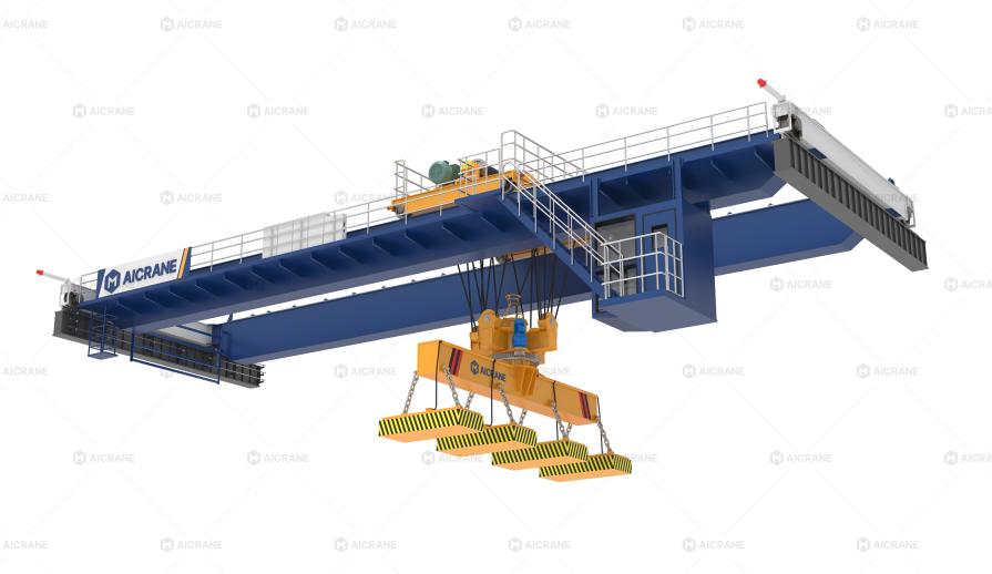
    Before beginning any civil or structural works, it is essential to understand the load requirements of the crane. A 30 ton overhead crane has a lifting capacity of 30 metric tons, but the actual loads the structure will endure are significantly higher due to dynamic factors such as acceleration, deceleration, impact loads, and trolley positioning.

    Design Load Considerations Include:

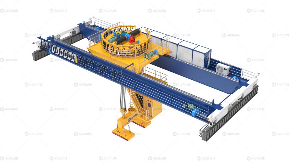
    • Static Load: The weight of the crane itself including the bridge, trolley, hoist, and end trucks.

    • Dynamic Load: Additional forces caused by acceleration and deceleration of the crane and hoist. For a 30-ton crane, the dynamic load can increase the actual stress on the support structure by 25-50%.

    • Load Distribution: End trucks transfer the load to the runway beams, which then transfer it to the columns and ultimately to the foundation. Accurate load distribution calculations are vital to avoid structural failure.

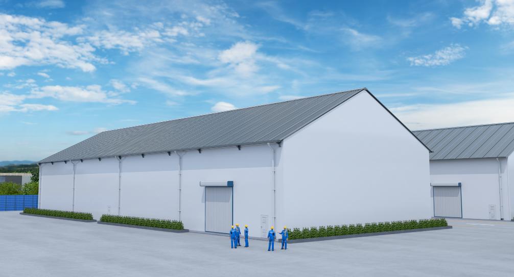
    2. Civil Works for Overhead Crane Installation

    Civil works provide the foundation and groundwork necessary for a safe crane installation. This includes preparing the floor, constructing the crane runway, and ensuring proper drainage and environmental protection.

    a. Foundation Construction

    The foundation is one of the most critical elements in overhead crane installation. For a 30-ton crane, the foundation must be designed to support the vertical loads from the crane, horizontal forces from braking and acceleration, and torsional forces from uneven loading.

    Key Elements of Foundation Design:

    • Load-Bearing Capacity: The foundation must be able to support the combined weight of the crane and the maximum dynamic load without excessive settlement. Soil tests are often conducted to determine the bearing capacity.

    • Reinforced Concrete Foundations: Foundations are typically made of reinforced concrete with steel reinforcement bars (rebar) to increase strength. For a 30-ton crane, foundations may include deep footings or pile foundations depending on soil conditions.

    • Foundation Dimensions: The size of the foundation must be calculated based on crane load, rail spacing, and floor slab thickness. Larger cranes generally require wider and deeper foundations to prevent tilting or differential settlement.

    • Anchor Bolts: Strong anchor bolts embedded in the foundation secure the crane runway rails. High-strength bolts are necessary to resist both shear and tensile forces.

    b. Floor Preparation

    The floor under and around the crane must be level, durable, and able to withstand heavy point loads. Industrial floors often consist of high-strength concrete slabs reinforced with steel mesh. For a 30-ton crane:

    • The floor thickness is typically 250-300 mm, reinforced with high-yield steel.

    • Expansion joints may be included to accommodate thermal expansion and prevent cracking.

    • Surface finishing ensures smooth movement of crane wheels and minimizes wear.

    c. Environmental and Safety Considerations

    Civil works should also consider environmental and operational safety:

    • Drainage Systems: Prevent water accumulation that could weaken the foundation or cause corrosion.

    • Seismic Reinforcement: In earthquake-prone areas, foundations and support structures should be designed to resist seismic forces.

    • Fire Protection: Concrete and steel structures may require fireproofing in high-risk industrial environments.

    30 ton bridge crane

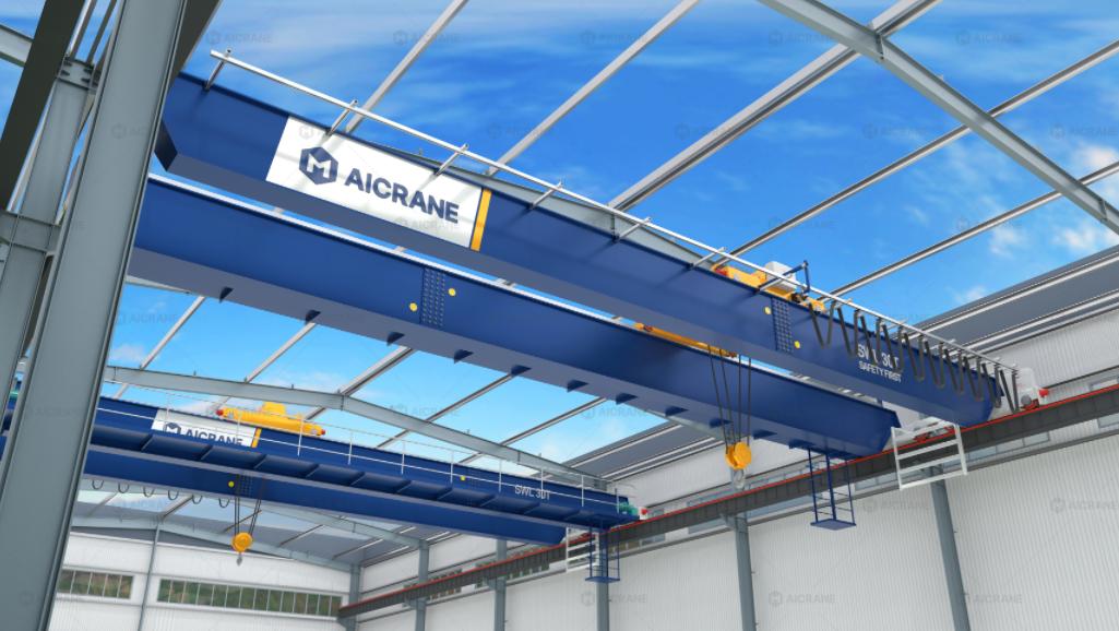
    3. Structural Reinforcement for Crane Support

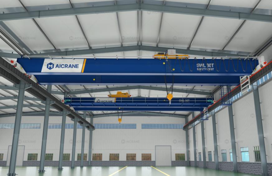
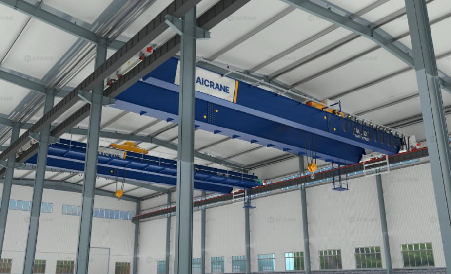
    The structural reinforcement of the steel structure workshop is equally crucial. For a 30-ton overhead crane, the roof beams, columns, and crane runway girders must withstand substantial forces.

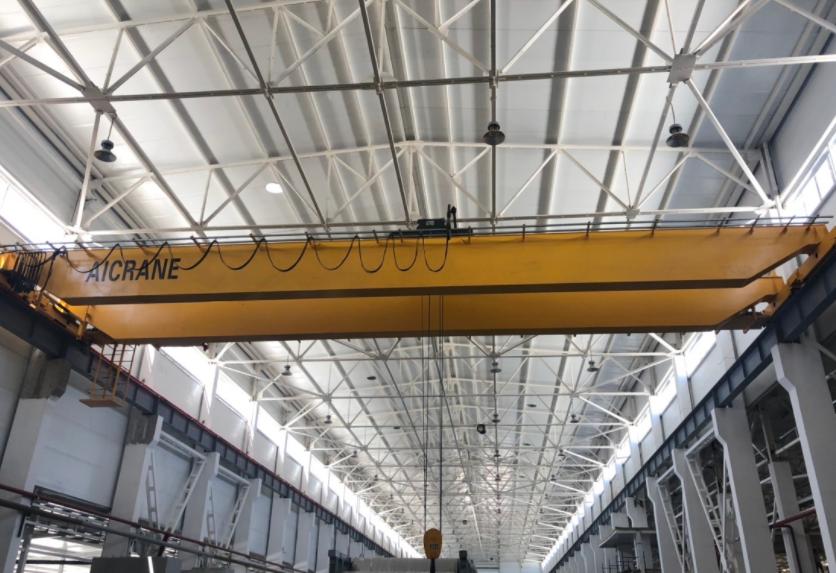
    a. Crane Runway Beams

    The runway beams carry the load of the crane along the building length and transfer it to the columns. These beams must be carefully designed:

    • Material Selection: Typically, high-strength steel sections such as I-beams or box girders are used.

    • Deflection Control: Excessive deflection can impair crane performance. For a 30-ton crane, allowable deflection is often limited to L/800 to L/1000, where L is the span of the beam.

    • Rail Support: Crane rails are welded or bolted to the top flange of the beams. Proper alignment and secure fixing are essential to prevent rail movement under load.

    b. Building Columns and Bracing

    The building’s vertical columns support the runway beams and must be reinforced to handle the crane loads:

    • Strengthening Existing Columns: If the building is retrofitted for a new crane, existing columns may require additional steel plates, concrete jackets, or bracing to meet load requirements.

    • Bracing: Diagonal or horizontal bracing reduces lateral sway and increases the rigidity of the structure. This is critical for maintaining crane stability during operation.

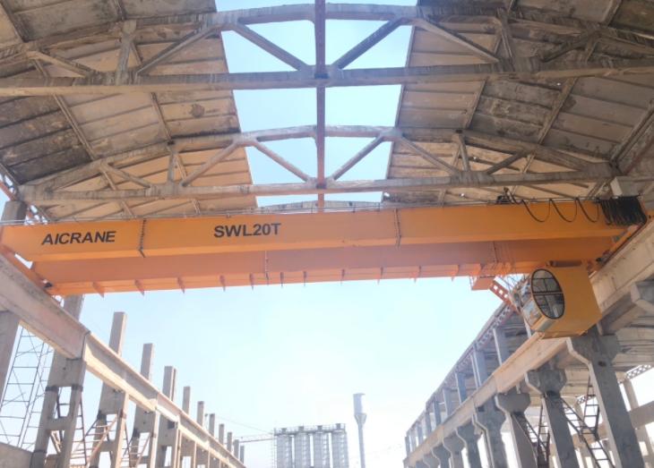
    c. Roof and Overhead Clearance

    A 30-ton crane has substantial height requirements. Structural reinforcement may involve:

    • Adjusting roof trusses to provide clearance for the crane hook at maximum lifting height.

    • Ensuring the crane bridge does not interfere with ventilation ducts, lighting, or other equipment.

    4. Installation and Alignment

    After completing civil works and structural reinforcement, the crane installation can proceed. Key steps include:

    • Rail Installation: Crane rails are laid on the reinforced runway beams and precisely leveled.

    • Bridge Assembly: The crane bridge is lifted into place, aligned, and secured.

    • Trolley and Hoist Installation: The trolley and hoist system are mounted and tested.

    • Load Testing: The crane is subjected to load tests, usually 125% of its rated capacity, to ensure safe operation.

    5. Maintenance Considerations

    Proper civil works and structural reinforcement reduce maintenance costs and extend crane lifespan. Routine inspections of runway rails, foundation cracks, and structural integrity are essential to detect wear or stress early. Reinforced foundations and steel beams also reduce vibrations, prolonging the service life of the crane components.

    6. Retrofitting Existing Structures

    In many cases, installing a 30-ton overhead crane involves retrofitting an existing building. Structural engineers evaluate the building’s load-bearing capacity and may recommend:

    • Adding steel columns or beams to support the crane.

    • Installing tie rods or bracing for lateral stability.

    • Strengthening floor slabs with concrete overlays or rebar reinforcement.

    Conclusion

    The installation of a 30-ton overhead crane is a complex project that requires detailed planning, precise civil works, and comprehensive structural reinforcement. Foundations, runway beams, columns, and floor slabs must all be engineered to withstand heavy dynamic loads and ensure long-term operational safety. Neglecting any aspect of civil or structural preparation can lead to crane misalignment, excessive deflection, or even catastrophic failure.

    By investing in well-designed civil works and reinforced structures, manufacturers and industrial facilities can ensure that their 30-ton overhead crane operates safely, efficiently, and reliably for decades, ultimately improving productivity and safeguarding personnel and equipment.

  • How to Handle Emergency Situations with Rubber Tyred Gantry Cranes

    Rubber Tyred Gantry (RTG) cranes are critical assets in container terminals, intermodal yards, and logistics hubs, designed to efficiently lift and transport containers across large working areas. However, like any heavy equipment, RTG cranes can face unexpected emergency situations ranging from equipment malfunctions to environmental hazards and operational accidents. Properly handling these emergencies is vital to protect personnel, cargo, and equipment while ensuring continuity of operations. This article explores common emergency scenarios, outlines best practices for response, and highlights the importance of training, planning, and technology in minimizing risks.

    rubber tyred gantry crane

    Common Emergency Situations in RTG Crane Operation

    Before discussing response strategies, it’s important to understand the types of emergencies that can arise in RTG crane operations:

    1. Power Failures – RTGs may experience sudden loss of electrical power due to grid failure, generator malfunction, or fuel shortages in hybrid models.

    2. Mechanical Failures – Issues such as hoist brake malfunction, trolley derailment, or gantry drive failure can suddenly stop operations and compromise safety.

    3. Electrical Malfunctions – Short circuits, control system errors, or PLC (Programmable Logic Controller) failures can render the tyre mounted gantry crane inoperable.

    4. Load Emergencies – Overloaded containers, dropped loads, or swinging loads due to operator error or strong winds.

    5. Weather-related Hazards – High winds, lightning, heavy rain, or earthquakes can put cranes and operators at risk.

    6. Fire Emergencies – Fires can occur due to overheating electrical systems, fuel leaks in diesel generators, or hydraulic oil ignition.

    7. Operator or Personnel Injury – Accidents involving crane operators or ground personnel during lifting or container positioning.

    Understanding these possible scenarios allows terminal operators to prepare structured emergency plans.

    Emergency Preparedness: The First Line of Defense

    Preparation is the key to minimizing risks during emergencies. Every port or container yard operating RTG cranes should have a documented Emergency Response Plan (ERP) that outlines step-by-step actions in various crisis situations. Key elements of preparedness include:

    • Training and Drills: Operators and ground staff must be trained in emergency shutdown, evacuation, and communication protocols. Regular drills help maintain readiness.

    • Clear Communication Channels: Two-way radios or digital communication systems must be available to instantly alert supervisors and emergency response teams.

    • Accessible Emergency Equipment: Fire extinguishers, spill kits, first aid stations, and emergency power backup should be strategically located around the yard.

    • Signage and Markings: Emergency stop buttons, escape routes, and safe assembly points should be clearly marked.

    Step-by-Step Response to Key Emergency Situations

    1. Power Failures

    In case of a power outage, the operator should:

    • Immediately activate the emergency brake systems to secure the load.

    • Communicate with the control room to notify of the power failure.

    • Avoid attempting to move the crane until backup power or repairs are provided.

    • If the crane is equipped with a diesel generator or hybrid system, switch to alternative power supply following proper procedures.

    2. Mechanical or Electrical Failures

    When mechanical or electrical issues occur:

    • Operators must stop all crane movement immediately using the emergency stop (E-stop) function.

    • Secure the load in its current safe position if possible.

    • Report the malfunction to the maintenance team without attempting makeshift repairs.

    • Evacuate the operator cabin if the situation poses a risk of collapse, fire, or electrical hazard.

    3. Load Emergencies

    Load-related emergencies are particularly dangerous:

    • If a load begins to sway uncontrollably, the operator should avoid sudden braking or acceleration, instead allowing controlled stabilization.

    • In case of overload detection, modern RTGs are equipped with overload limiters that automatically halt hoisting; operators must follow protocols to lower the load safely once systems allow.

    • If a container slips or falls, halt operations immediately, secure the site, and provide first aid or emergency response if personnel are affected.

    RTG crane

    4. Weather Hazards

    RTGs are highly vulnerable to weather conditions:

    • During high winds, operators should lower containers to the ground and park the movable gantry crane in a designated safe area with storm locks engaged.

    • In case of lightning storms, operators should stop work and seek shelter away from the crane, as cranes can act as lightning conductors.

    • In earthquakes, operators should stop the crane, lower the load if possible, and evacuate to a safe zone.

    5. Fire Emergencies

    A fire in an RTG crane can spread quickly due to hydraulic oil or fuel:

    • Operators should immediately hit the emergency stop button and evacuate the cabin.

    • Use fire extinguishers if the fire is small and manageable; otherwise, wait for professional responders.

    • Shut down nearby cranes or equipment to prevent the fire from spreading.

    • Report the incident to fire response teams and supervisors.

    6. Personnel Accidents

    If an operator or ground worker is injured:

    • Stop all crane operations immediately.

    • Secure the area to prevent additional injuries.

    • Provide first aid and call medical responders without delay.

    • File an incident report and review procedures to prevent recurrence.

    Role of Technology in Emergency Handling

    Modern RTG cranes are equipped with advanced technologies that significantly improve safety and emergency response:

    • Emergency Stop (E-stop) Systems: Multiple E-stop buttons are placed on the crane to instantly halt movement.

    • Overload Protection Devices: Prevent lifting beyond rated capacity.

    • Anti-Sway Systems: Reduce load swinging, minimizing risks in windy conditions or sudden stops.

    • Remote Monitoring: Control rooms can monitor crane parameters in real time, identifying issues before they escalate.

    • Fire Detection and Suppression Systems: Automatic extinguishers can control fires in electrical cabinets or engine compartments.

    Training and Continuous Improvement

    Handling emergencies effectively requires more than just equipment and procedures; it depends on people. Continuous operator training should include:

    • Emergency evacuation drills.

    • Simulation-based training for load emergencies and power failures.

    • Regular refresher courses on fire safety and first aid.

    • Cross-training of staff so multiple people can respond in critical situations.

    In addition, every emergency should be followed by a post-incident review to analyze causes, assess response effectiveness, and implement corrective actions.

    Conclusion

    Rubber Tyred Gantry cranes are indispensable in modern port and logistics operations, but their scale and complexity mean that emergencies can have serious consequences if not properly managed. From power outages and mechanical failures to severe weather and fire hazards, operators and yard managers must be prepared for a wide range of scenarios. A combination of thorough preparation, structured emergency response protocols, advanced safety technologies, and continuous training ensures that emergencies are handled swiftly and safely. Ultimately, proactive planning not only protects personnel and equipment but also safeguards operational continuity in high-demand container handling environments.

  • The Impact of Steel Prices on 20 Ton Gantry Crane Cost

    When businesses consider investing in heavy lifting equipment such as a 20-ton gantry crane, one of the most significant cost drivers is the price of steel. Steel is the primary raw material used in gantry crane manufacturing, accounting for a large proportion of the total production cost. Because steel markets are highly volatile and influenced by global supply and demand, price fluctuations can have a direct and often substantial impact on the cost of gantry cranes. For companies planning to purchase or upgrade cranes, understanding the relationship between steel prices and equipment costs is crucial for effective budgeting, negotiation, and timing of investment.

    20 ton gantry crane

    Why Steel Prices Matter in Gantry Crane Manufacturing

    A 20 ton gantry crane is a medium-to-heavy-duty lifting solution widely used in construction, manufacturing, shipbuilding, logistics, and warehouse operations. Its structural framework—main girders, end beams, supporting legs, and trolley rails – is made primarily from high-strength steel. In fact, steel typically represents 40–60% of the crane’s total manufacturing cost, depending on the model, customization, and additional features such as cantilevers, rails, or enclosed cabins.

    This makes steel prices a critical factor in the final cost of a gantry crane. If steel prices rise sharply, manufacturers often have no choice but to pass on part of that increase to customers. Conversely, when steel prices fall, buyers may enjoy more competitive offers, provided that demand and production costs in other areas remain stable.

    The Global Steel Market and Its Volatility

    Steel prices fluctuate due to a variety of factors, including:

    1. Raw material costs – The prices of iron ore, coking coal, and scrap metal are key inputs in steel production. Any shortage or price increase in these materials can drive steel prices upward.

    2. Global demand and supply – Countries like China, India, and the U.S. are major steel producers and consumers. When infrastructure spending increases or when global supply tightens, steel prices climb.

    3. Energy prices – Steel production is energy-intensive. Rising electricity and fuel costs increase steelmaking expenses, which influence the final steel price.

    4. Trade policies and tariffs – Import/export restrictions, tariffs, or anti-dumping duties on steel can lead to sudden regional price shifts.

    5. Currency fluctuations – Since steel is traded globally, exchange rate volatility also impacts steel prices, particularly for international buyers.

    Because of these factors, gantry crane manufacturers face continuous challenges in maintaining stable pricing for their products.

    Direct Impact on 20 Ton Gantry Crane Costs

    A 20-ton gantry crane typically requires dozens of tons of high-quality steel, depending on its span, height, and whether it is a single girder or double girder configuration. Even small changes in steel prices can significantly alter the crane’s cost. Let’s look at how steel price fluctuations affect the final price:

    1. Material Cost Share
      If steel accounts for 50% of the total production cost of a gantry crane, a 10% increase in steel price could raise the crane’s cost by around 5%. For large industrial purchases, this percentage translates into thousands of dollars.

    2. Customization Impact
      Customized cranes, such as those with longer spans, additional cantilevers, or reinforced girders for heavy-duty work, require more steel. As a result, the impact of steel price fluctuations is even more pronounced for custom-built 20-ton cranes.

    3. Supplier Adjustments
      Manufacturers often update crane quotations every few months to reflect steel price changes. Buyers who delay orders during a steel price surge may find that their final quote is significantly higher than expected.

    4. Spare Parts and Maintenance
      Beyond the initial purchase, steel price fluctuations also affect the cost of replacement parts – rails, wheels, beams, or supports. Over time, this increases the total cost of ownership for a gantry crane.

    20 ton gantry crane price

    Indirect Effects of Steel Price Changes

    While the direct link between steel prices and crane cost is clear, there are also indirect effects to consider:

    • Extended Lead Times
      When steel is in short supply, crane manufacturers may experience delays in production schedules, resulting in longer lead times for delivery.

    • Financing and Budgeting Challenges
      Companies may struggle to finalize budgets if steel-driven cost increases make price forecasting unpredictable.

    • Competitive Pressures
      Some suppliers may absorb part of the steel cost increase to remain competitive, while others pass the entire burden to the buyer. This creates variation in market pricing.

    Strategies for Buyers to Manage Steel Price Impact

    Businesses looking to purchase a 20-ton gantry crane are not powerless against steel market volatility. There are several strategies that can help reduce risk:

    1. Timing Purchases Wisely
      Monitoring steel market trends allows buyers to time their purchases when prices are relatively low. For example, ordering cranes during periods of global oversupply can secure better deals.

    2. Negotiating Fixed Price Contracts
      Some manufacturers may agree to lock in steel prices at the time of contract signing, protecting buyers from price fluctuations before delivery.

    3. Comparing Multiple Suppliers
      Since different manufacturers have different sourcing strategies, comparing offers can reveal price variations even in a high steel cost environment.

    4. Exploring Alternative Designs
      Depending on operational needs, buyers can choose between single girder and double girder cranes, or optimize span and lifting height, which affects the amount of steel required and ultimately the crane price.

    5. Long-Term Supplier Partnerships
      Establishing a trusted relationship with crane manufacturers can ensure better transparency on cost breakdowns and allow for more favorable pricing arrangements.

    Case Example: Steel Price Surge and Crane Procurement

    Consider a logistics company planning to install a 20-ton double girder gantry crane in a port facility. The initial quotation from the supplier was based on a steel price of $600 per ton. Three months later, global steel prices jumped to $750 per ton due to increased demand in Asia and disruptions in supply chains. As a result, the double girder gantry crane price increased by nearly 8%. The company, facing budget constraints, decided to negotiate a phased delivery with the supplier to spread costs over time.

    This example illustrates how steel price volatility can force buyers to adapt their procurement strategies quickly to avoid financial strain.

    Outlook for Buyers in 2025 and Beyond

    Looking forward, steel markets are expected to remain volatile due to continued uncertainties in global trade, decarbonization efforts in steelmaking, and fluctuating energy costs. Buyers of 20-ton gantry cranes should anticipate that steel price changes will remain a key cost factor. Investing time in market analysis, supplier discussions, and purchase planning will be critical to controlling expenses.

    Conclusion

    The cost of a 20-ton gantry crane is closely tied to steel prices, which are influenced by raw material availability, global demand, energy costs, trade policies, and currency exchange rates. For buyers, these fluctuations can significantly affect both the upfront investment and the long-term cost of ownership. By understanding the dynamics of steel markets and adopting strategies such as timing purchases, negotiating contracts, and building long-term supplier relationships, businesses can better manage the financial impact of steel price volatility.

    Ultimately, informed decision-making is the best safeguard against unpredictable cost increases. As steel remains the backbone of gantry crane manufacturing, keeping an eye on its market trends is essential for any company planning to invest in lifting solutions.

  • 500 Ton Gantry Cranes: Specialized Uses and Engineering Challenges

    Gantry cranes are among the most essential lifting equipment in industrial operations, enabling the movement of heavy and oversized loads with precision and efficiency. While gantry cranes are available in various capacities—from a few tons to several hundred tons—the 500-ton gantry crane represents a highly specialized category, designed for extremely heavy-duty applications. These cranes are integral in industries such as shipbuilding, power generation, heavy engineering, and large-scale infrastructure projects. However, their immense lifting capacity brings with it significant engineering challenges, requiring meticulous design, planning, and operational considerations.

    500 ton gantry crane

    Specialized Uses of 500 Ton Gantry Cranes

    1. Shipbuilding and Offshore Platforms

    One of the most prominent applications of 500 ton gantry cranes is in the shipbuilding industry. Shipyards frequently handle large ship blocks, hull sections, and modules weighing hundreds of tons. A single ship block can easily exceed 400 tons, necessitating the use of cranes capable of safely lifting and maneuvering these structures.

    In offshore engineering, the construction of oil rigs and wind turbine platforms often involves heavy prefabricated sections. Gantry cranes with a 500-ton capacity can handle these massive components with precision, ensuring that modules are correctly aligned during assembly.

    2. Power Plant Construction

    Power plants—especially nuclear and thermal facilities—require the movement of enormous machinery and structural components. Steam generators, turbines, condensers, and large heat exchangers often weigh several hundred tons. A 500-ton gantry crane enables the safe and efficient lifting of these components from transport vehicles to their installation positions within the plant.

    The ability to handle such massive loads reduces reliance on multiple smaller cranes, improving workflow efficiency and minimizing project timelines.

    3. Heavy Industrial Manufacturing

    Industries producing heavy machinery, industrial presses, and mining equipment often rely on high-capacity gantry cranes. A 500-ton crane can lift large molds, casting parts, and assembly modules for manufacturing heavy-duty machinery. In steel production plants, for instance, these cranes assist in moving massive slabs, rolls, and furnaces that would otherwise require complex multi-crane arrangements.

    4. Bridge and Infrastructure Projects

    Large infrastructure projects, such as suspension bridges or long-span highway bridges, require the handling of massive girders and precast concrete segments. A 500-ton gantry crane can lift and precisely place these enormous structural elements, reducing assembly time and improving safety by minimizing manual handling.

    In railway infrastructure, these cranes are often used to lift and position large track segments, concrete sleepers, and overhead support structures for high-speed rail lines or heavy freight corridors.

    500 ton gantry crane for sale

    Engineering Challenges in Designing 500 Ton Gantry Cranes

    While the applications of 500-ton gantry cranes are diverse and crucial, designing and operating such cranes is a highly complex engineering task. The challenges involve structural integrity, stability, material selection, safety systems, and operational efficiency.

    1. Structural Design and Material Selection

    A crane with a 500-ton capacity must have a robust structural framework capable of withstanding not only the vertical load but also dynamic forces during lifting and movement.

    • Main girder design: The main girder must resist bending and torsional stresses. Engineers often use box girders or truss structures made from high-strength steel to achieve the required stiffness and strength while keeping the weight manageable.

    • Leg and support structures: The crane’s legs must support the massive loads and transmit them safely to the foundation or rails. Reinforced steel with careful welding and bolting practices ensures durability and safety.

    Material selection is critical. High-grade structural steels with excellent yield strength and fatigue resistance are essential to prevent permanent deformation or failure under repeated heavy loads.

    2. Stability and Load Distribution

    At such high capacities, stability becomes a paramount concern. Even slight deviations in load distribution or unexpected forces, such as wind gusts, can compromise the crane’s safety.

    • Counterweight systems: To maintain balance, engineers often incorporate counterweights that offset the load being lifted, reducing the risk of tipping.

    • Load moment calculations: Precise calculations of load moments, factoring in cantilevered extensions or asymmetrical loads, are necessary to prevent structural overstress.

    • Foundation engineering: The foundation or rail system supporting the crane must withstand enormous vertical and horizontal forces. In some cases, reinforced concrete pads or deep pile foundations are used to ensure stability.

    3. Hoisting Mechanisms and Safety Systems

    The hoisting system is one of the most critical components in a 500-ton gantry crane.

    • Multi-rope hoists: Lifting massive loads requires multiple wire ropes operating simultaneously. The synchronization of these ropes is critical to avoid uneven lifting and stress concentrations.

    • Hydraulic or electric drives: High-capacity cranes may use electric or hydraulic drive systems capable of controlling both speed and load smoothly. Precision control reduces dynamic loading and enhances safety.

    • Load monitoring: Advanced sensors and load monitoring systems ensure that the crane never exceeds its rated capacity. Overload detection, sway prevention, and automated emergency braking are standard safety measures.

    4. Wind and Environmental Considerations

    Outdoor operations introduce additional engineering challenges. Wind loads, temperature variations, and seismic activity can affect crane stability.

    • Wind load analysis: Large goliath cranes act like sails, and wind can induce significant lateral forces. Engineers must conduct wind load simulations and may incorporate aerodynamic design features to reduce these effects.

    • Seismic design: In earthquake-prone regions, the crane and its foundation must meet strict seismic criteria to prevent catastrophic failure.

    5. Operational Challenges

    Operating a 500-ton gantry crane is not just about engineering design; it also involves significant operational considerations:

    • Precision handling: Lifting massive loads requires careful maneuvering, often guided by sophisticated control systems that allow operators to make precise adjustments.

    • Maintenance demands: Regular inspections and maintenance are vital. Even minor wear on cables, hoists, or structural components can pose safety risks.

    • Training: Operators require specialized training to handle high-capacity cranes safely, including emergency response procedures and load management strategies.

    Conclusion

    A 500-ton gantry crane represents a pinnacle of industrial lifting capability, serving specialized roles in shipbuilding, power generation, heavy manufacturing, and large-scale infrastructure projects. Its ability to handle enormous loads with precision enhances efficiency, reduces project timelines, and enables construction and manufacturing feats that would be impossible with smaller cranes.

    However, the engineering and operational challenges associated with such cranes are formidable. From structural integrity and material selection to stability, hoisting mechanics, and environmental considerations, every aspect of design and operation must be meticulously planned and executed. Advanced safety systems, precise load monitoring, and rigorous maintenance protocols are essential to ensure reliable performance and prevent catastrophic failures.

    Ultimately, the 500-ton gantry crane is not merely a lifting machine – it is a testament to engineering excellence, combining structural ingenuity, mechanical sophistication, and operational precision to meet the demands of some of the world’s most challenging industrial applications. As industries continue to push the boundaries of scale and complexity, these cranes will remain indispensable tools in achieving engineering and construction milestones.

  • Smart Collision Avoidance Systems in Rubber Tyred Gantry Crane Operations

    Rubber Tyred Gantry (RTG) cranes are pivotal in container terminals, shipyards, and heavy industrial facilities for efficient container handling and cargo movement. These cranes, with their mobility and lifting capacity, dramatically increase terminal productivity. However, their operation involves complex movements within crowded environments – posing risks of collisions with other cranes, vehicles, infrastructure, or personnel.

    To mitigate these risks and improve operational safety, smart collision avoidance systems (CAS) have become essential in modern RTG crane operations. These systems leverage cutting-edge sensors, automation, and intelligent algorithms to prevent accidents, protect assets, and optimize workflow.

    This article explores the technology behind smart collision avoidance systems for rubber tyred gantry RTG cranes, their components, benefits, and practical considerations for implementation.

    rubber tyred gantry crane

    1. The Importance of Collision Avoidance in RTG Operations

    RTG cranes operate in dynamic environments where multiple cranes, trucks, and personnel move simultaneously in tight spaces. The challenges include:

    • Limited visibility for operators due to crane size and height.

    • Narrow aisle spacing between containers.

    • High crane speeds during repositioning.

    • Frequent simultaneous operations involving multiple cranes.

    These factors increase the risk of collisions that can lead to:

    • Equipment damage with costly repairs.

    • Injury or fatality risks to workers.

    • Operational delays and reduced terminal throughput.

    • Increased insurance and liability costs.

    A collision avoidance system acts as a critical safety net to detect, warn, and prevent potential collisions before they occur.

    2. What Are Smart Collision Avoidance Systems?

    Smart Collision Avoidance Systems are advanced safety technologies integrated into RTG cranes to continuously monitor surroundings and crane movements. They use a combination of sensors, communication networks, and intelligent processing to:

    • Detect obstacles and nearby cranes or vehicles.

    • Calculate collision risk based on relative speed and trajectory.

    • Alert operators visually and audibly.

    • Automatically intervene by slowing or stopping crane movements to prevent collisions.

    Unlike basic alarm systems, smart CAS are proactive, adaptive, and integrated with crane control systems for real-time decision-making.

    3. Core Components of RTG Collision Avoidance Systems

    A typical smart collision avoidance system for RTG cranes comprises the following components:

    3.1 Sensors

    • Radar Sensors: Emit radio waves to detect objects and measure distance.

    • LiDAR (Light Detection and Ranging): Use laser pulses for precise 3D mapping of nearby objects.

    • Ultrasonic Sensors: Detect obstacles at close range using sound waves.

    • Cameras: Provide visual data for object recognition and operator assistance.

    • GPS and RTK Positioning: Track precise crane location and movement in real time.

    3.2 Data Processing Unit

    • Central computer processes sensor inputs.

    • Applies algorithms to identify obstacles, predict trajectories, and assess collision risks.

    3.3 Communication Network

    • Wireless communication between cranes, vehicles, and control centers.

    • Facilitates data sharing and coordination among multiple cranes.

    3.4 Operator Interface

    • Visual displays and audible alarms to notify crane operators.

    • User-friendly HMI (Human-Machine Interface) panels integrated into crane cabins.

    3.5 Automated Control Integration

    • Links with the crane’s drive and braking system.

    • Enables automatic speed reduction or emergency stop to avoid collisions.

    RTG rubber tyred gantry crane

    4. How Smart Collision Avoidance Systems Work in RTG Cranes

    The operation follows a typical sequence:

    1. Continuous Environment Scanning: Sensors monitor the crane’s surrounding area for obstacles, other cranes, trucks, or personnel.

    2. Data Fusion and Analysis: The system fuses inputs from multiple sensors to create a comprehensive picture, filtering noise and false alarms.

    3. Trajectory Prediction: Using speed, direction, and position data, the system predicts the paths of the crane and potential obstacles.

    4. Collision Risk Assessment: If predicted paths intersect within a critical safety margin, the system identifies a collision risk.

    5. Operator Alert: Warnings such as flashing lights, sound alarms, or dashboard indicators notify the operator of the hazard.

    6. Automatic Intervention: If the operator does not respond, the system can slow down or halt the movable gantry crane automatically to prevent impact.

    7. Continuous Monitoring: The system continuously updates predictions and actions until the hazard passes.

    5. Benefits of Smart Collision Avoidance Systems for RTG Cranes

    5.1 Enhanced Safety

    • Significantly reduces the risk of collisions, protecting operators, ground workers, and equipment.

    • Prevents accidents that can cause severe injuries or fatalities.

    5.2 Increased Equipment Longevity

    • Avoids costly damage to expensive RTG cranes, spreaders, and containers.

    • Reduces wear and tear caused by abrupt impacts.

    5.3 Improved Operational Efficiency

    • Minimizes downtime due to accident investigations and repairs.

    • Enables cranes to operate closer together safely, maximizing terminal throughput.

    5.4 Better Regulatory Compliance

    • Meets international and local safety standards and guidelines.

    • Demonstrates commitment to workplace safety and risk management.

    5.5 Data Collection and Analytics

    • Collects operational data to analyze near-misses and optimize crane movement strategies.

    • Supports predictive maintenance and operational planning.

    6. Challenges and Considerations in Implementation

    6.1 Integration Complexity

    • Collision avoidance systems must integrate seamlessly with existing crane control systems.

    • Customization is often required based on terminal layout and operational protocols.

    6.2 Environmental Factors

    • Harsh weather, dust, rain, or fog can affect sensor performance, particularly optical systems like LiDAR or cameras.

    • Systems need to be robust and possibly combined with multiple sensor types for reliability.

    6.3 Operator Training

    • Operators must understand system alerts and how to respond appropriately.

    • Training on new safety protocols and system interfaces is essential.

    6.4 False Alarms and Sensitivity Settings

    • Overly sensitive systems can cause nuisance alarms, disrupting workflow.

    • Calibration and tuning are needed to balance safety with operational fluidity.

    6.5 Cost and ROI

    • Initial investment can be substantial, but long-term savings from accident prevention and operational efficiency justify the cost.

    7. Future Trends in Collision Avoidance for RTG Cranes

    The evolution of smart collision avoidance continues with innovations such as:

    • Artificial Intelligence and Machine Learning: For better object recognition and predictive analytics.

    • V2X Communication: Vehicle-to-everything networking for real-time coordination among cranes, trucks, and yard systems.

    • Augmented Reality (AR) Interfaces: To provide operators with intuitive, heads-up collision warnings and guidance.

    • 5G Connectivity: For ultra-low latency communication supporting instantaneous system responses.

    • Fully Autonomous RTG Cranes: Where collision avoidance is foundational to self-driving crane operations.

    Conclusion

    Smart collision avoidance systems are transforming Rubber Tyred Gantry crane operations by significantly elevating safety, efficiency, and equipment longevity in container terminals and industrial yards. By integrating sophisticated sensors, real-time data processing, and automated controls, these systems proactively prevent accidents in environments where the stakes are high.

    As terminal operators increasingly prioritize automation and digitalization, investing in advanced collision avoidance technology is no longer optional but essential. With careful planning, system integration, and operator training, smart collision avoidance systems can deliver measurable returns in safety performance and operational productivity – making RTG crane operations safer and smarter than ever before.

  • The Role of Safety Factors in Overhead Crane Capacity Design

    Overhead cranes are vital equipment in many industrial settings, from manufacturing plants and warehouses to shipyards and construction sites. Their primary function is to lift, move, and position heavy loads safely and efficiently. Ensuring the safety and reliability of these cranes is paramount because any failure can lead to severe accidents, equipment damage, costly downtime, and even loss of life. One fundamental concept integral to the design and operation of overhead cranes is the use of safety factors in determining crane capacity.

    This article explores the role of safety factors in overhead crane capacity design, why they are essential, how they are applied, and their impact on crane performance and safety.

    overhead crane capacity

    Understanding Safety Factors

    What Is a Safety Factor?

    A safety factor (also known as a factor of safety, or FoS) is a multiplier applied during the design process to account for uncertainties, variabilities, and potential unforeseen stresses beyond the nominal load the crane is expected to handle. It ensures that the crane’s components and structure can support loads greater than the maximum rated load without failure.

    For example, a safety factor of 1.5 means that the crane is designed to withstand 1.5 times the rated maximum load safely.

    Why Are Safety Factors Needed?

    Several reasons justify the use of safety factors in overhead travelling crane design:

    • Material Variability: Real-world materials may have slight inconsistencies in strength and quality compared to theoretical values.

    • Dynamic Effects: Loads are rarely static; starting, stopping, acceleration, and load sway cause dynamic forces that exceed static weights.

    • Wear and Tear: Over time, fatigue, corrosion, and mechanical wear reduce the structural capacity.

    • Human Error: Operator mistakes or rigging errors can introduce unexpected stresses.

    • Environmental Conditions: Wind, temperature fluctuations, and seismic activity impose additional loads.

    • Uncertainty: Unknown or unaccounted factors during operation require a margin of safety.

    Application of Safety Factors in Crane Capacity Design

    Determining Rated Capacity

    The rated capacity of an overhead crane is the maximum load it can safely lift under normal operating conditions, considering safety factors. Engineers start by calculating the theoretical maximum load based on structural analysis, material properties, and mechanical components, then apply a safety factor to derive a conservative, safe working limit.

    Typical Safety Factor Ranges

    Safety factors for overhead cranes generally range from 1.25 to 2.0, depending on:

    • Crane Type: Overhead cranes with less precise control or used in harsher environments require higher safety factors.

    • Duty Classification: Cranes with higher duty cycles (more frequent use or heavy loading) use larger safety factors.

    • Standards and Regulations: Different standards specify minimum safety factors, such as CMAA, ASME, ISO, and EN standards.

    For instance, the CMAA Specification No. 70 suggests safety factors of 1.5 for most overhead cranes, while specialized cranes under extreme conditions may require even higher margins.

    Safety Factors for Structural vs. Mechanical Components

    • Structural Components: Girders, end trucks, columns, and welds typically have safety factors to handle static and dynamic stresses and fatigue.

    • Mechanical Components: Hoists, brakes, wire ropes, and gears have safety factors based on their material strength, wear limits, and failure modes.

    overhead crane lifting capacity

    How Safety Factors Influence Design Decisions

    1. Material Selection and Dimensions

    To meet required safety factors, engineers may select higher-grade steels or alloys and increase the thickness or cross-sectional dimensions of structural members. This increases strength and stiffness, allowing the crane to support higher loads with a safety margin.

    2. Component Sizing and Redundancy

    Components such as wire ropes and brake systems are sized to exceed expected loads by safety factors, and sometimes redundancy is introduced—for example, dual brakes or multiple wire ropes—to ensure continued operation even if one fails.

    3. Control Systems and Operational Limits

    Safety factors also guide the design of control systems:

    • Overload Protection: Devices such as load sensors and limit switches prevent lifting beyond rated capacity.

    • Emergency Stops: Systems designed to engage quickly if unsafe conditions arise.

    • Operational Alarms: Warning systems alert operators to approach safety limits.

    4. Inspection and Maintenance Schedules

    Higher safety factors allow longer intervals between maintenance but cannot replace the need for regular inspections. Structural components and mechanical parts are periodically checked for wear, corrosion, and fatigue, ensuring the safety factor is not compromised over time.

    Safety Factors and Real-World Operating Conditions

    Accounting for Dynamic Loading

    Lifting operations involve forces beyond the static weight of the load. Starting, stopping, swinging, and sudden movements generate dynamic effects that increase stresses significantly. Safety factors ensure the crane structure and components tolerate these conditions without damage.

    Environmental and Site Influences

    • Wind Loads: Wind can apply lateral forces that combine with lifting loads, demanding higher safety margins.

    • Temperature Variations: Temperature changes affect material strength and elasticity, necessitating design allowances.

    • Seismic Activity: In earthquake-prone regions, cranes may require additional safety factors and design modifications to resist seismic forces.

    Safety Factors in Standards and Codes

    International and regional standards incorporate safety factors into their requirements:

    • CMAA Specification 70: Sets minimum safety factors for various crane classes, addressing structural and mechanical design.

    • ASME B30.2: Provides operational safety requirements, including load ratings and safety factors.

    • ISO 4301: Offers a classification system that influences the selection of safety factors based on crane duty and usage.

    Adherence to these standards ensures that cranes meet regulatory safety requirements and minimize risk.

    Impact on Cost and Performance

    Trade-Offs Between Safety and Cost

    Applying larger safety factors improves reliability and reduces risk but increases material use, weight, and costs. Overdesigning may also reduce operational efficiency due to heavier cranes requiring more powerful motors and larger foundations.

    Optimizing Safety Factors

    Modern design methods, including finite element analysis (FEA) and real-time monitoring, enable engineers to optimize safety factors—balancing safety, cost, and performance rather than relying on overly conservative estimates.

    Case Study: Safety Factors in a 30-Ton Overhead Crane

    A 30 ton overhead crane designed for a manufacturing plant incorporated a safety factor of 1.5. During detailed analysis, engineers accounted for:

    • Dynamic amplification of up to 1.3 times due to load acceleration.

    • Environmental factors like moderate wind loads inside the facility.

    • Expected fatigue over a 20-year lifespan.

    This led to selecting ASTM A992 steel girders with increased thickness and high-strength wire ropes rated at 45 tons. Overload detection systems and emergency brakes were installed to enhance safety. After installation, the crane demonstrated reliable performance with no structural issues during regular inspections, confirming the effectiveness of the safety factor design.

    Conclusion

    Safety factors play a crucial role in the design of overhead crane capacities. They provide essential margins that account for uncertainties, dynamic forces, environmental conditions, and operational variability, ensuring cranes operate safely and reliably over their service life. Properly applied safety factors influence material selection, structural design, mechanical component sizing, and control system development, while also guiding maintenance and inspection protocols.

    Balancing adequate safety margins with cost efficiency is a key engineering challenge. Advances in analysis techniques and monitoring technologies help optimize safety factors for modern crane designs, improving both safety and operational performance. Ultimately, understanding and applying safety factors correctly protects lives, equipment, and productivity in every overhead crane operation.

  • Selecting Motors and Gearboxes for 20 Ton Overhead Cranes

    Overhead cranes play a vital role in heavy-duty industrial environments by handling and transporting loads efficiently and safely. Among them, 20-ton overhead cranes are a common configuration for medium to heavy lifting across various sectors such as manufacturing, steel plants, shipyards, and logistics. One of the most critical elements in ensuring reliable crane operation lies in the correct selection of motors and gearboxes. These components directly impact the crane’s lifting capacity, speed, energy efficiency, durability, and operational precision.

    This article explores the key considerations, technical specifications, and decision-making criteria involved in selecting the right motors and gearboxes for 20 ton overhead cranes.

    20 ton overhead crane

    Understanding the Role of Motors and Gearboxes

    1. Motors: Power Source for Movement

    Electric motors serve as the primary power source for crane operations, driving the hoisting, trolley, and bridge traveling motions. Depending on the motion, different types and power ratings of motors may be used within the same crane system.

    2. Gearboxes: Torque and Speed Conversion

    Gearboxes are critical for translating the high-speed output of the motor into a torque-optimized, low-speed motion suited for lifting and positioning heavy loads. They also help reduce mechanical strain and improve control over crane operations.

    Types of Motors Used in 20 Ton Overhead Cranes

    1. Squirrel Cage Induction Motors

    These are the most commonly used motors due to their ruggedness, low maintenance, and good efficiency. They are widely applied in bridge and trolley traveling mechanisms.

    2. Wound Rotor Motors

    These are preferred in applications requiring adjustable speed and high starting torque, such as in hoisting mechanisms of 20-ton cranes. They can be connected with resistors or used with frequency converters for better performance control.

    3. Servo Motors (Optional in Advanced Cranes)

    High-performance cranes equipped with automation systems may use servo motors in specific motions to achieve superior precision, especially in positioning tasks.

    Motor Selection Criteria

    When choosing motors for a 20-ton overhead crane, consider the following:

    1. Power Rating (kW)

    Motor power should be selected based on load requirements, duty cycle, and desired lifting speed. For a 20-ton hoist with moderate speed and duty class A5 or A6, the motor power typically ranges from 15 to 45 kW.

    2. Duty Class

    Cranes are classified by working duty (A1–A8). For example, A5–A6 indicates moderate to heavy usage, which affects motor sizing and thermal protection. Motors in higher-duty cranes must withstand frequent starts/stops and continuous operation.

    3. Starting Torque

    A high starting torque is essential for hoisting motors to lift 20 tons from rest. Gear motor assemblies must be optimized to avoid lag or slippage under full load.

    4. Efficiency and Energy Use

    Energy-efficient motors (IE2 or IE3 class) are preferable in modern systems to reduce operational costs and comply with energy regulations.

    5. Integration with VFDs

    Motors compatible with Variable Frequency Drives (VFDs) allow smooth start, stop, and speed variation – critical for reducing mechanical wear and improving load handling precision.

    20 ton overhead crane for sale

    Gearbox Types for Overhead Cranes

    1. Helical Gearboxes

    Known for high efficiency and smooth operation, helical gearboxes are widely used in hoisting and trolley mechanisms. They offer excellent load capacity and compact design.

    2. Planetary Gearboxes

    Used in high-torque applications where compactness is key. They are ideal for the hoisting mechanism of 20-ton cranes, especially in confined installations.

    3. Bevel-Helical Gearboxes

    These combine the benefits of bevel and helical gears, suitable for bridge and trolley travel with right-angle orientation.

    Gearbox Selection Criteria

    1. Torque Capacity

    Gearboxes must deliver sufficient torque to lift 20-ton loads, accounting for inertia, acceleration, and load variations.

    2. Gear Ratio

    The required gear ratio depends on lifting/traveling speed and motor RPM. Typical lifting speeds range from 3–8 m/min for 20-ton cranes. A properly calculated ratio ensures smooth and safe operations.

    3. Gearbox Mounting Type

    Depending on the crane design (open winch or compact hoist), the gearbox may be foot-mounted, flange-mounted, or integrated with the motor in a gear motor assembly.

    4. Thermal Capacity

    Gears generate heat during operation. Adequate cooling (fan-cooled or oil-cooled) is essential to maintain performance in continuous operation.

    5. Shock Load Tolerance

    Since overhead cranes encounter dynamic load changes, the gearbox must be designed to absorb shock loads without premature wear.

    Integration of Motors and Gearboxes

    For optimal performance, motors and gearboxes must be matched precisely in terms of:

    • Shaft alignment and couplings

    • Torque and speed compatibility

    • Load profile and acceleration requirements

    • Duty cycle synchronization

    • Environmental protection (IP rating and thermal class)

    Using pre-engineered gear motor units simplifies installation and ensures factory-tested integration for reliability.

    Environmental and Safety Considerations

    • IP Protection: Motors and gearboxes must be protected against dust, moisture, and oil ingress, with IP54 or higher recommended in industrial settings.

    • Brake Systems: Motor brakes (electromagnetic or spring-loaded) are vital for safe stopping of heavy loads.

    • Overload Protection: Motors must include thermal sensors and gearboxes should have overload protection mechanisms.

    • Temperature Range: In harsh environments, motor and gearbox components should be rated for high or low temperatures (e.g., -20°C to +60°C).

    Example Configuration for a 20 Ton Overhead Crane

    • Hoisting Motor: 30 kW wound rotor motor with VFD, duty class A6

    • Hoisting Gearbox: Planetary gearbox with 25:1 ratio, torque rating 5000 Nm

    • Traveling Motors: 2×5.5 kW squirrel cage motors with brake and encoder

    • Traveling Gearboxes: Helical gearboxes, right-angle, 12:1 gear ratio

    • Control System: Integrated PLC with VFD control and load monitoring

    Maintenance and Lifecycle Considerations

    Proper motor and gearbox selection also reduces long-term maintenance. Key practices include:

    • Regular lubrication of gears

    • Monitoring bearing temperatures

    • Checking motor windings and insulation

    • Scheduled replacement of oil seals and brake linings

    • Vibration analysis to detect early faults

    High-quality gearboxes and motors with service-friendly designs minimize downtime and enhance crane longevity.

    Conclusion

    Choosing the right motors and gearboxes for a 20-ton overhead crane is essential for achieving operational efficiency, safety, and reliability. Factors such as power requirements, duty class, torque capacity, gear ratios, and environmental conditions must be carefully analyzed. Integrating motors and gearboxes with smart control systems and ensuring proper maintenance further enhances the overall performance of the overhead crane.

    By investing in high-performance, properly matched components, businesses can ensure that their 20-ton overhead cranes deliver long-term value and dependable service across demanding industrial applications.

  • Turnkey Solutions: Steel Structure and Overhead Crane Package Delivery

    In the fast-evolving industrial landscape, efficiency, reliability, and integration are critical factors in facility construction and equipment installation. For industries relying on heavy lifting and material handling – such as manufacturing, logistics, steel fabrication, and warehousing – the combination of steel structures and overhead cranes forms the backbone of their operational capabilities. Delivering these two essential components as a turnkey package offers significant advantages in terms of time savings, cost control, and seamless integration.

    This article explores the concept of turnkey solutions involving steel structures and overhead cranes, explains why such integrated delivery is becoming a preferred approach, outlines the key steps in the process, and highlights best practices for ensuring a successful project outcome.

    steel structure

    What is a Turnkey Solution?

    A turnkey solution refers to a comprehensive package where a single supplier or contractor manages the entire process of design, fabrication, supply, installation, and commissioning of a complete system or facility. The client receives a ready-to-use, fully functional product or infrastructure with minimal additional input needed.

    In the context of steel structures combined with overhead cranes, a turnkey package typically includes:

    • Design and engineering of the steel building structure

    • Fabrication and erection of the steel frame

    • Design, manufacture, and supply of the overhead crane system (single girder, double girder, or specialized cranes)

    • Installation of crane runway beams integrated with the steel structure

    • Electrical wiring, control systems, and testing of the crane

    • Final commissioning and handover

    By contracting a single provider for the entire project, clients benefit from streamlined coordination, unified project management, and reduced interface risks between structure and crane suppliers.

    Overhead Crane in Steel Structure Factory

    Why Choose Turnkey Package Delivery?

    1. Simplified Project Management

    Coordinating separate vendors for steel structure and overhead cranes can be complex and prone to delays or conflicts in schedules and specifications. A turnkey provider acts as the single point of contact, managing every detail from structural design through crane commissioning, ensuring timelines are met and communication flows smoothly.

    2. Design Integration and Compatibility

    Steel structures and overhead cranes must work in perfect harmony to ensure safety, performance, and durability. For example, the crane runway beams need to be precisely designed and fabricated to carry crane loads safely without compromising the structural integrity of the building. With turnkey delivery, structural engineers and crane specialists collaborate early in the design phase, guaranteeing compatibility and optimal performance.

    3. Cost Efficiency

    Bundling steel structure and crane supply into one contract can lead to cost savings by reducing duplicated engineering work, optimizing material usage, and negotiating package discounts. Additionally, better project scheduling prevents costly downtime and delays on site.

    4. Quality Assurance

    A single provider is accountable for the entire scope, which encourages stringent quality control throughout fabrication and installation. This reduces the risk of defects or mismatched components and results in a safer, more reliable facility.

    5. Faster Delivery Time

    Turnkey projects benefit from coordinated workflows and reduced administrative burden, enabling faster completion from contract award to operational readiness. This speed-to-market can be critical in competitive industries where downtime directly impacts revenue.

    The Turnkey Package Delivery Process

    Step 1: Needs Assessment and Feasibility Study

    The turnkey provider begins by engaging with the client to understand operational requirements, budget constraints, site conditions, and timeline expectations. This phase includes preliminary site surveys, load capacity analysis, and reviewing any regulatory compliance needs.

    Step 2: Conceptual and Detailed Design

    Engineers from both steel structure and overhead crane teams collaborate on creating an integrated design. This involves:

    • Steel frame calculations to ensure the building supports all static and dynamic loads, including crane loadings

    • Designing runway beams, columns, and bracing systems capable of safely transferring crane loads to foundations

    • Selecting the appropriate crane type (single/double girder, electric, hydraulic, etc.) based on lifting capacity, span, and duty cycle

    • Preparing structural drawings, crane layout plans, and wiring diagrams

    At this stage, 3D modeling and BIM (Building Information Modeling) tools are often used to visualize and validate the design.

    Step 3: Procurement and Fabrication

    Once designs are approved, material procurement begins. The steel structure components are fabricated in specialized workshops using CNC cutting, welding, and painting processes to ensure precision and durability. Simultaneously, the overhead crane components – including girders, hoists, trolleys, motors, control panels – are manufactured and tested.

    Step 4: Site Preparation and Erection

    Before steel structure erection, the site must be prepared with foundations and concrete footings designed to withstand crane loads. After that:

    • Steel columns and beams are assembled and erected on site according to detailed erection plans

    • Crane runway beams are installed with tight tolerance requirements to ensure smooth crane operation

    • The overhead crane is assembled and installed on the runway beams, including wiring, control systems, and safety devices

    Close collaboration between steel erectors and crane installers is crucial during this phase.

    Step 5: Testing and Commissioning

    Comprehensive testing ensures the crane and structure operate safely and reliably. This includes:

    • Load testing the crane with test weights

    • Verifying alignment and smooth travel of crane hoist and trolley

    • Testing control responsiveness and emergency stops

    • Inspecting steel structure connections for any signs of stress or deformation

    Only after all checks are passed does the turnkey provider hand over the fully operational system to the client.

    Key Considerations for Turnkey Package Delivery

    Regulatory Compliance and Standards

    Steel structures and overhead cranes are subject to strict codes and standards, such as AWS, ISO, FEM, CMAA, and local building regulations. The turnkey provider must ensure all designs, materials, and processes meet or exceed these requirements.

    Customization vs. Standardization

    While standard crane models and steel structures can reduce costs, many clients require customized solutions to fit unique site conditions or operational needs. Turnkey suppliers should offer flexible design options to accommodate various industry demands.

    Future Expansion and Maintenance

    Clients should discuss potential future expansion with the turnkey provider to design structures and cranes that can be upgraded or extended easily. Additionally, clear maintenance and service plans should be included in the turnkey contract.

    Risk Management

    Turnkey contracts often come with fixed pricing and deadlines. Providers must have robust risk management plans to handle unexpected site issues, supply chain disruptions, or design changes without compromising quality or schedule.

    Case Study: A Successful Turnkey Delivery for a Steel Fabrication Plant

    A recent example highlights the benefits of turnkey delivery. A steel fabrication client required a 30-meter span workshop equipped with a double girder overhead crane 20 ton for heavy load handling.

    The turnkey supplier conducted a thorough site survey and designed a steel structure with integrated crane runway beams. Fabrication and installation were coordinated tightly, resulting in:

    • 25% reduction in project duration compared to separate contracts

    • 15% cost savings through material and labor optimization

    • Flawless integration with no post-installation modifications needed

    The client reported immediate operational benefits and praised the single-source responsibility model for simplifying project management.

    Conclusion

    Turnkey solutions for steel structures combined with overhead cranes present a compelling value proposition for industrial clients aiming to enhance operational efficiency and reduce project complexity. From integrated design and quality-controlled fabrication to coordinated installation and commissioning, turnkey delivery offers significant benefits in terms of cost, time, and performance.

    When selecting a turnkey provider, clients should focus on experience, technical expertise, compliance capabilities, and proven track records in handling complex steel and crane projects. A well-executed turnkey package is more than just a building and a crane – it’s a turnkey asset that supports long-term productivity and safety.

  • Engineering Considerations for Future Overhead Crane Capacity Expansion

    As industrial operations scale and evolve, the lifting requirements in many facilities grow accordingly. An overhead crane that adequately serves a facility today may become under-capacity in just a few years due to changes in production volume, heavier components, or larger machinery. Planning for future overhead crane capacity expansion is not just about selecting a bigger crane; it involves a series of thoughtful engineering considerations to ensure scalability, efficiency, and safety. This article explores the critical engineering aspects to consider when preparing for future capacity upgrades in overhead crane systems.

    overhead crane capacity

    1. Understanding Current and Future Lifting Needs

    The first step in planning for capacity expansion is to thoroughly evaluate both current operational demands and foreseeable future requirements. This involves:

    • Analyzing Load Profiles: Determine the range, average, and peak load weights currently being lifted and estimate how these values might change in the coming 5 to 10 years.

    • Anticipating Product or Equipment Changes: If the production line is expected to include heavier components or larger modules, this should be factored into crane design.

    • Frequency of Use: Higher usage rates in the future may necessitate a higher duty classification, stronger components, and more robust systems.

    2. Structural Design of Runways and Building

    The runway beams and building structure that support the crane are foundational components that must be engineered with foresight:

    • Crane Runway Beams: The runway system (rails, support beams, and brackets) must be designed to withstand potential future loads. Undersized runways are difficult and costly to upgrade once installed.

    • Column and Foundation Design: Support columns and foundations should be engineered to accommodate higher vertical and lateral forces from a future upgraded crane.

    • Building Height and Clearances: Ensure that there is adequate headroom and side clearance to accommodate a large overhead crane or higher-lifting hoist system in the future.

    3. Crane Classification and Duty Cycle

    The crane duty class (A1–A8 as per FEM/ISO or CMAA standards) defines how frequently and intensively the crane will be used. As operations scale, the crane may need to shift from a light-duty (e.g., A3) to a medium- or heavy-duty class (e.g., A5 or A6):

    • Load Spectrum: A heavier or more variable load profile might require a crane with stronger mechanical and electrical components.

    • Upgrading Motors and Brakes: Consider motors, brakes, and gearboxes that can handle higher loads and more frequent operations.

    4. Scalability of Hoisting and Trolley Systems

    If an upgrade is expected, choosing a modular hoist and trolley system can significantly reduce future downtime and costs:

    • Hoist Capacity: Select a hoist with a serviceable or upgradeable motor, gearbox, and drum capable of handling higher loads.

    • Trolley Configuration: A double-rail trolley may offer better flexibility for future upgrades compared to a single-girder monorail system.

    • Auxiliary Hoists: Installing an auxiliary hoist initially can allow the main hoist to be upgraded later while maintaining production continuity.

    5. Bridge Girder Design for Expansion

    Bridge girders are one of the most critical components in overhead crane systems:

    • Double Girder vs. Single Girder: Double girders typically offer better capacity and are easier to reinforce or adapt for future upgrades.

    • Material Selection: Use high-strength steel or materials that allow for additional bracing or reinforcement in future upgrades.

    • Pre-Engineered Girder Strength: Even if a lower-capacity crane is installed initially, the girders can be engineered for higher loads so only the hoist needs upgrading later.

    bridge crane capacity

    6. Electrical Systems and Controls

    The electrical system should be designed to accommodate future upgrades in power requirements and control options:

    • Power Supply: Use electrical panels, festoon systems, and conductors that support higher amperage for future load increases.

    • Variable Frequency Drives (VFDs): Installing VFDs now can offer smoother operation, energy efficiency, and compatibility with higher-capacity motors later.

    • Scalable Control Systems: PLCs (programmable logic controllers) and remote-control systems should be chosen with expansion in mind, allowing for more inputs and outputs in the future.

    7. Load Testing and Safety Factors

    To ensure long-term safety, overhead crane for sale must be engineered with suitable safety margins and tested appropriately:

    • Design Safety Factors: Design for at least 25-50% more than the initial load capacity, depending on the expected upgrades.

    • Load Path Integrity: All elements in the load path – from hoist to hook to runway beam – must be structurally cohesive to support future loads.

    • Future Load Testing: Schedule periodic load testing and condition assessments to ensure the structure is ready for capacity increases.

    8. Maintenance and Access Considerations

    Planning for future expansion should also include how the system will be maintained or modified:

    • Ease of Access: Ensure cranes, runways, and control systems are easily accessible for inspections, maintenance, and upgrades.

    • Replaceable Components: Use bolted (not welded) joints where feasible to ease component replacement.

    • Maintenance Records: Keep comprehensive logs to track stress, wear, and performance over time to support future upgrade decisions.

    9. Regulatory and Compliance Requirements

    Expanding crane capacity requires adherence to industry standards and local regulations:

    • Design Codes: Follow international standards such as FEM, CMAA, or ISO for structural and mechanical design.

    • Permit Considerations: In many regions, increasing crane capacity may trigger new permit requirements or inspection mandates.

    • Third-party Certification: It may be necessary to involve a third-party inspection body to certify the crane after capacity expansion.

    10. Cost vs. Benefit Analysis

    It’s essential to weigh the cost of overbuilding now versus the cost of a retrofit or replacement later:

    • Initial Overbuild: Slightly higher initial investment for expandable or oversized components may prevent costly downtime in the future.

    • Retrofit Cost: Retrofitting a crane system post-installation may involve downtime, structural reinforcement, and expensive new parts.

    • Life-Cycle Cost: Consider the entire life cycle of the crane system when evaluating upfront costs versus future expansion potential.

    Conclusion

    Engineering for future overhead crane capacity expansion is a proactive approach that saves time, cost, and operational headaches down the line. By considering scalability in runway and structural design, hoist and girder configurations, electrical systems, and maintenance access, facilities can ensure their lifting systems remain effective even as production requirements evolve. With proper planning, today’s overhead crane investment can seamlessly adapt to meet tomorrow’s challenges, providing long-term value and operational continuity.

  • Structural Design for EOT Cranes with Rotating Hoist or Slewing Mechanism

    Electric Overhead Travelling (EOT) cranes are widely used across industries for their ability to handle heavy materials with precision and reliability. In advanced applications, EOT cranes may be equipped with a rotating hoist or slewing mechanism, offering greater flexibility in load positioning and orientation. These features, however, introduce new structural and mechanical challenges that must be carefully addressed during the design phase.

    This article explores the key structural design considerations for EOT cranes with rotating hoist or slewing mechanisms, including their functionality, load implications, support structures, and integration within industrial facilities.

    EOT Crane with Rotating Hoist

    1. Understanding Rotating Hoist and Slewing Mechanisms

    Before diving into structural aspects, it is essential to understand the role of rotating and slewing systems in electric overhead travelling cranes:

    • Rotating Hoist: A hoist mechanism that can rotate the lifted load along a vertical axis, often through a rotating hook or gearbox. It allows operators to precisely position and orient loads without moving the entire crane bridge or trolley.

    • Slewing Mechanism: Typically integrated into the crane trolley or bridge, it allows the hoist or an entire segment of the crane to pivot, either through a slewing ring or bearing assembly. This system is common in jib cranes and portal cranes, but advanced EOT cranes may also incorporate it.

    These mechanisms are used in applications such as:

    • Assembly lines requiring load reorientation

    • Precise placement of cylindrical or asymmetric parts

    • Handling of components in confined spaces

    2. Structural Design Considerations: General Overview

    EOT cranes with slewing or rotating hoist functions involve dynamic forces and moments that differ from conventional crane systems. The structural design must accommodate:

    • Torsional moments due to rotating masses

    • Eccentric loading when loads are rotated off-center

    • Increased lateral and longitudinal forces due to slewing

    • High-precision alignments for bearing assemblies

    The crane structure must be robust enough to resist these additional loads without compromising safety, service life, or accuracy.

    EOT Crane with Slewing Mechanisms

    3. Design of Crane Girder and Trolley Frame

    a. Torsional Rigidity

    In a standard EOT overhead crane for sale, the bridge girder primarily deals with vertical bending. However, a rotating hoist introduces torsional loading due to eccentric rotation of the load. This requires:

    • Use of box girders or I-beams with torsional reinforcements

    • Additional diagonal bracings or stiffeners

    • Finite element analysis (FEA) to predict deformation under dynamic rotation

    b. Reinforced Trolley Frame

    The trolley frame, which carries the rotating hoist or slewing gear, must withstand:

    • Radial and axial forces from the slewing bearing

    • Vibrations and dynamic impacts during rotation

    • Load imbalances caused by off-center rotation

    Reinforced trolley structures with welded box-type construction are preferred to handle these loads.

    4. Slewing Ring or Bearing Integration

    The slewing bearing is one of the most critical components in rotating hoist systems. Structurally, its housing and mounting area must be:

    • Flat and aligned to prevent uneven wear

    • High in rigidity to resist tilting or bending

    • Properly bolted and torque-controlled to maintain structural integrity

    Often, designers add a steel base plate and bearing support ribs to distribute loads uniformly across the trolley.

    5. Rotational Torque and Counterforces

    When a load rotates, especially with a slewing mechanism, it creates torque reactions that transfer into the crane’s structural system. The design must account for:

    • Resisting torque through structural braces or counterweights

    • Bearing block reinforcements

    • Anti-rotation devices or locking systems for stability when idle

    Additionally, torsional impact from sudden stops or emergency braking should be modeled during load simulations.

    6. Runway Beam and Crane Rail Alignment

    The runway beams supporting the crane must be designed for not only vertical wheel loads but also horizontal thrust caused by:

    • Slewing or rotating loads shifting the center of gravity

    • Braking or acceleration torque from the rotating mechanism

    This requires:

    • Robust crane runway beams with lateral bracing

    • High-strength rail clips and bolts

    • Checking deflection limits under combined loading scenarios

    Improper alignment could lead to rail deformation, increased wheel wear, or derailment.

    7. Support Columns and Building Integration

    When installing rotating hoist EOT cranes in steel structure buildings, the support columns and overall building frame must be assessed for:

    • Dynamic side loads

    • Asymmetric loading scenarios

    • Fatigue due to frequent rotation and torsion

    In many cases, column stiffeners or additional bracing systems are added to improve stability. Coordination with building engineers is critical to ensure compatibility with the crane design.

    8. Motor, Gearbox, and Control Systems Placement

    The weight and location of the motor and gearbox for the slewing mechanism can shift the load center on the trolley or bridge. Structurally:

    • Their weight must be included in dead load calculations

    • Vibration dampening pads or base mounts may be required

    • Access platforms or maintenance walkways should be structurally supported

    Electrical cables, festoon systems, and rotating joints must also be protected from bending stresses during rotation.

    9. Dynamic Analysis and Simulation

    Advanced structural design must include:

    • Finite Element Analysis (FEA) to simulate stresses under slewing and rotation

    • Dynamic modeling to analyze how the crane structure responds to rotating loads, braking forces, and resonance

    • Fatigue life analysis for components experiencing repeated rotation and torque

    This ensures the crane meets both safety standards and long-term durability expectations.

    10. Safety and Compliance Standards

    Cranes with rotating mechanisms must meet additional safety and design standards, such as:

    • ISO 8686: Design loads for cranes

    • FEM 1.001: Classification of mechanisms

    • ASME B30.2: Overhead and gantry cranes

    • EN 13001: General design for cranes

    Safety devices must be integrated, including:

    • Slew angle limiters

    • Overload protection

    • Emergency stop for slewing

    • Anti-collision sensors

    11. Maintenance and Accessibility

    The structural design should also consider ease of maintenance, including:

    • Platforms or ladders for accessing slewing gears

    • Removable covers for inspection of rotating components

    • Support beams for handling or replacing the slewing motor or bearings

    Designing with maintenance in mind reduces downtime and improves operational safety.

    Conclusion

    Designing the structure of an EOT crane with a rotating hoist or slewing mechanism involves more than just scaling up standard crane designs. It demands a detailed analysis of torsional forces, dynamic loading, structural reinforcements, and mechanical precision. Each component—from the girder and trolley to the building support—must work in harmony to ensure the crane operates safely and effectively under all conditions.

    With the help of modern simulation tools, compliance standards, and experienced engineering teams, it is possible to integrate slewing and rotating capabilities into overhead cranes without compromising safety or performance. These advanced EOT crane systems enable more versatile material handling operations and play a crucial role in industries where precision and flexibility are paramount.