Category: Gantry Crane

  • RMG Crane Mechanical Coordination Between Hoisting, Trolley, and Traveling Systems

    Rail Mounted Gantry (RMG) cranes are pivotal in modern material handling operations, particularly in container terminals, logistics hubs, and industrial yards. Their primary advantage lies in their ability to transport heavy loads across wide areas while ensuring precise positioning. However, the effectiveness of an RMG crane depends heavily on the mechanical coordination between its three core systems: the hoisting mechanism, the trolley mechanism, and the traveling system. Understanding how these systems interact is essential for optimizing performance, minimizing wear, and ensuring safety. This article delves into the intricacies of this mechanical coordination, exploring each system and their interdependencies.

    RMG container crane

    1. Overview of RMG Crane Mechanisms

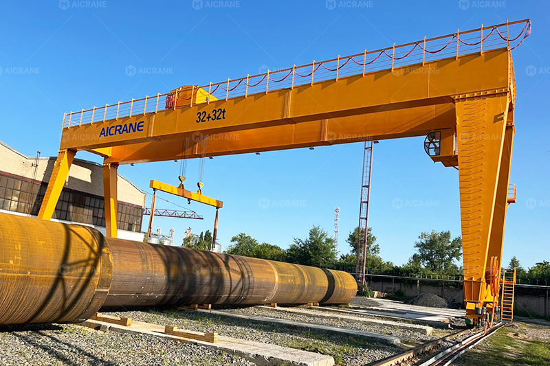
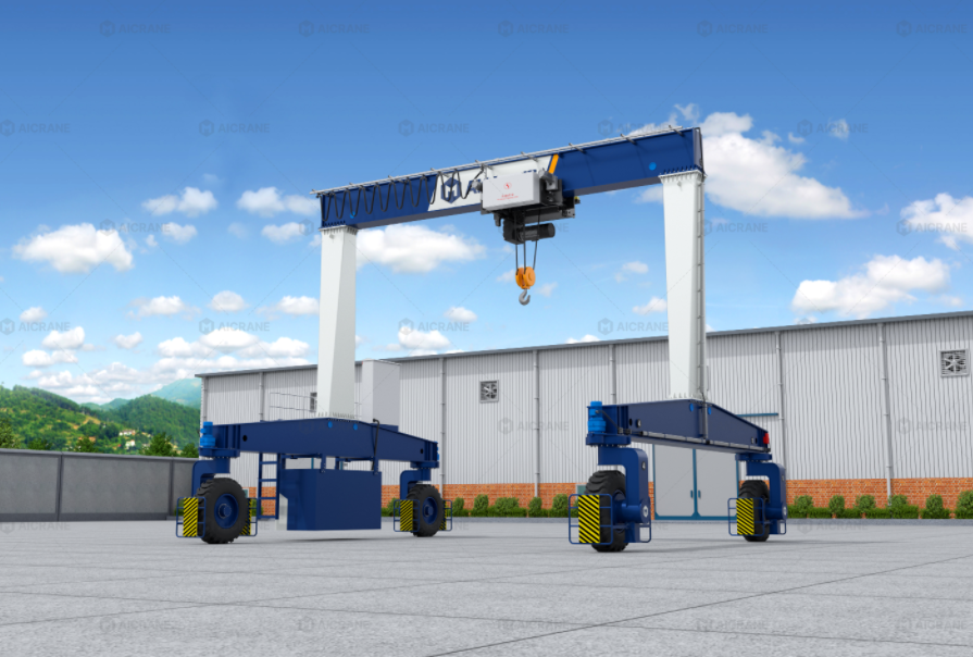
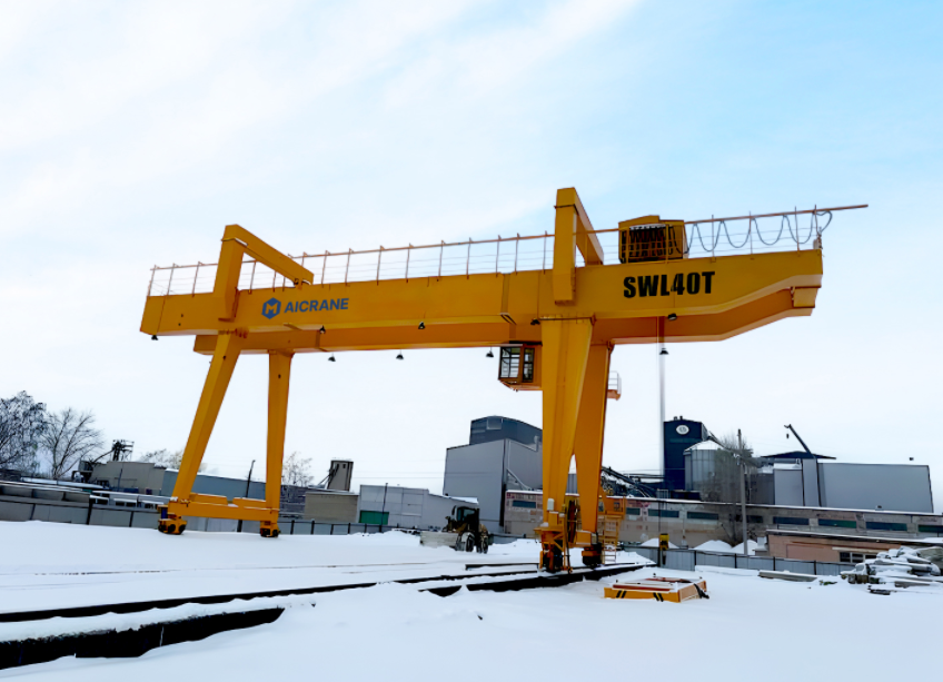
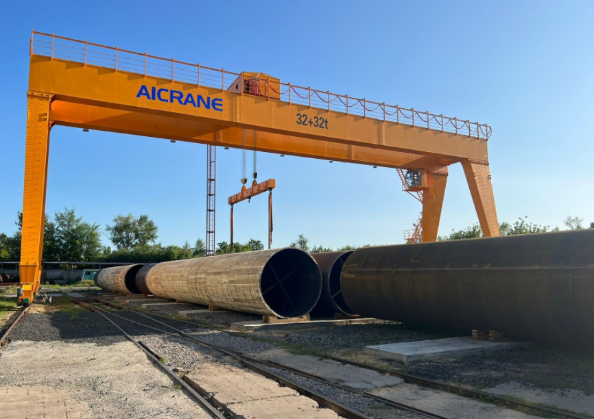
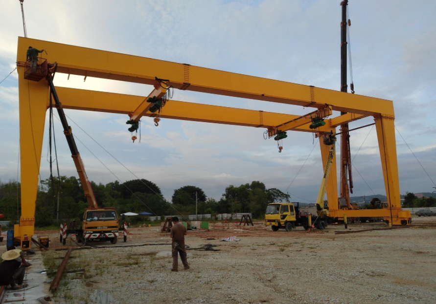
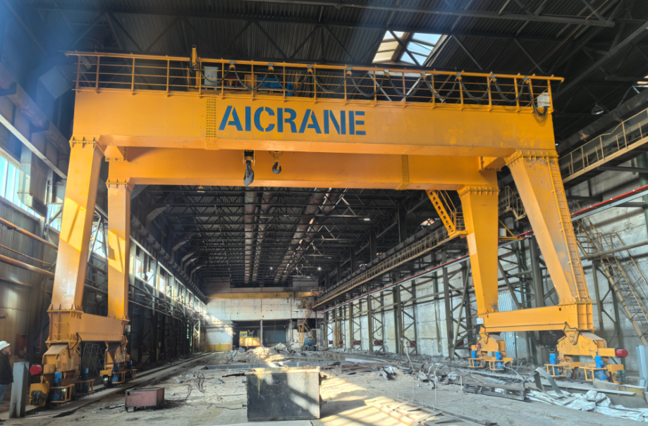
    A rail mounted gantry crane for sale essentially consists of a bridge supported by wheels that travel along rails, a trolley that moves along the bridge, and a hoist that lifts and lowers the load. Each mechanism operates independently yet must work harmoniously to achieve precise load handling. The three primary systems are:

    1. Hoisting System – Responsible for lifting and lowering the load. It usually includes a hoist drum, wire rope, motor, gearbox, and braking system.

    2. Trolley System – Moves the hoist along the bridge, providing lateral positioning of the load. The trolley is equipped with wheels, a drive system, and often a guiding system for smooth motion.

    3. Traveling System – Moves the entire crane along the runway rails, covering the longitudinal direction of the working area. It involves wheel bogies, drive motors, and sometimes steering or guidance mechanisms.

    While these systems are individually critical, the efficiency of an RMG crane hinges on how well they are coordinated.

    2. Hoisting System Dynamics

    The hoisting mechanism is the core lifting component of an RMG crane. It typically employs an electric or hydraulic motor to rotate a drum that winds or unwinds a wire rope, raising or lowering the hook or spreader. Key factors in the hoisting system include:

    • Load Capacity: The crane’s maximum lifting load dictates motor size, gearbox ratio, and rope specifications.

    • Speed Control: Smooth acceleration and deceleration prevent load sway and reduce mechanical stress. Variable frequency drives (VFDs) are commonly used for precise speed regulation.

    • Braking System: Mechanical, hydraulic, or electromagnetic brakes ensure the load remains stable when hoisting stops.

    • Wire Rope Coordination: For twin or multi-rope systems, synchronized rope movement is crucial to maintain balance and prevent torsion.

    The hoist must coordinate with the trolley and traveling systems, particularly when handling dynamic loads. For instance, rapid trolley movement while hoisting can generate swing or impact forces, requiring synchronized control to maintain stability.

    3. Trolley Mechanism Functionality

    The trolley mechanism allows the hoist to move horizontally along the bridge girder, enabling precise positioning over containers or cargo. Its main components include:

    • Trolley Wheels and Rails: Wheels designed for smooth motion along the bridge rails, often with flanges for lateral guidance.

    • Drive System: Electric motors with reduction gears provide controlled acceleration and deceleration.

    • Guidance and Alignment: Sensors or mechanical guides help keep the trolley aligned to avoid derailment or uneven load distribution.

    The trolley’s operation must be coordinated with hoisting because lateral motion of a lifted load can create oscillations. In modern RMG cranes, synchronization is often managed electronically through the crane control system, but mechanical design considerations remain critical:

    • Rigid Frame and Low Flexibility: The trolley frame must resist bending to avoid uneven load distribution across the hoist ropes.

    • Balanced Load Transfer: The trolley’s position affects how forces are transmitted to the bridge and traveling system. Incorrect alignment can lead to uneven rail loading and premature wear.

    RMG crane

    4. Traveling System Mechanics

    The traveling system moves the entire crane along the rails spanning the storage yard or terminal. It is composed of:

    • Bridge Wheels and Bogies: Wheels with appropriate flanges and bogies for weight distribution.

    • Drive Motors and Gearboxes: Ensure smooth acceleration, deceleration, and control at low speeds.

    • Braking Mechanism: Maintains stability during load handling or in emergencies.

    Traveling a crane while the hoist is carrying a load requires careful coordination. High-speed longitudinal travel can induce sway in a lifted load, increasing stress on the hoist ropes and trolley bearings. Therefore, mechanical design often incorporates:

    • Shock Absorbers or Dampers: Minimize impact forces on structural components.

    • Load Distribution Optimization: Ensures bridge wheels carry weight evenly to prevent rail or wheel damage.

    • Rigid Frame Design: The crane structure must resist twisting from uneven load forces during travel.

    5. Coordination Between Systems

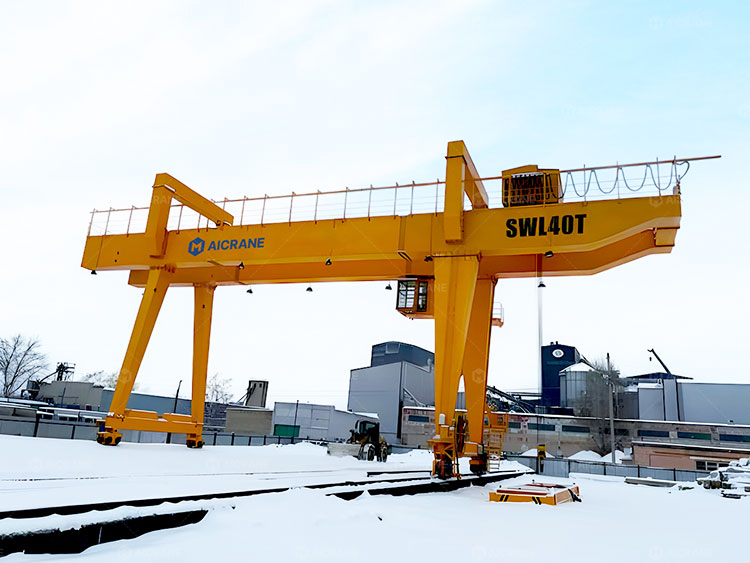
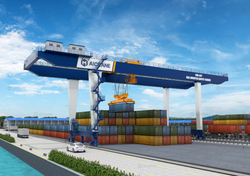
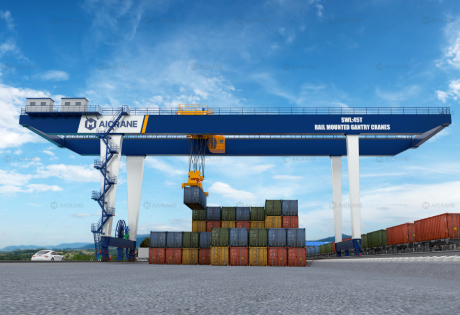
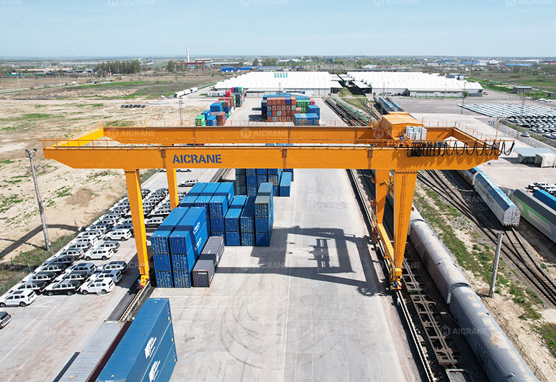
    The core challenge in rail mounted container gantry crane design is ensuring seamless mechanical coordination among hoisting, trolley, and traveling systems. Several principles govern this coordination:

    5.1 Load Transfer Path

    Every RMG crane must transfer load efficiently from the hoist to the trolley, then to the bridge, and finally to the traveling wheels. Any misalignment in this load path can lead to:

    • Excessive bending in the bridge girder

    • Premature wear on trolley wheels or hoist ropes

    • Load sway during travel, affecting operational safety

    5.2 Motion Synchronization

    When lifting and moving loads simultaneously, mechanical forces must be harmonized:

    • Hoisting and Trolley Coordination: As the hoist raises a container, the trolley’s acceleration should be gradual to prevent pendulum-like swinging.

    • Trolley and Traveling Coordination: Lateral movements combined with bridge travel must account for inertial forces. For heavy loads, traveling speed may need to be reduced to maintain load stability.

    • Hoist and Traveling Coordination: In some operations, hoisting while traveling can strain ropes and brakes. Advanced cranes use sensors to limit combined motion speeds.

    5.3 Structural Flexibility vs. Rigidity

    The crane’s frame and trolley must strike a balance between rigidity (to prevent deflection) and flexibility (to absorb dynamic forces). Excessive rigidity can transmit shocks directly to mechanical components, while too much flexibility can increase sway and reduce positional accuracy.

    6. Role of Control Systems in Mechanical Coordination

    While the focus here is mechanical, modern RMG cranes integrate sophisticated electronic control systems to complement mechanical design:

    • Interlocks: Prevent simultaneous motions that could destabilize the load.

    • Load Sensors: Detect uneven forces and adjust hoist or trolley speed.

    • Synchronization Algorithms: Ensure multiple motors and drives operate in harmony.

    These systems reduce the dependency on operator skill alone, improving safety and efficiency, while also mitigating mechanical stress.

    7. Maintenance Implications

    Proper mechanical coordination affects maintenance cycles:

    • Misaligned trolley wheels or bridge rails accelerate wear.

    • Uncoordinated motions increase rope fatigue and hoist drum wear.

    • Excessive dynamic forces can compromise structural integrity over time.

    Regular inspection of alignment, wheel bearings, hoist ropes, and brake systems is essential. Preventive maintenance ensures that mechanical coordination remains optimal, extending the crane’s operational lifespan.

    8. Conclusion

    The mechanical coordination between hoisting, trolley, and traveling systems defines the operational efficiency, safety, and reliability of RMG cranes. Each system must work not only independently but also in precise harmony with the others. The hoist provides vertical movement, the trolley facilitates lateral positioning, and the traveling system ensures longitudinal transport—all while transferring loads safely through the crane structure. Attention to load paths, motion synchronization, structural design, and maintenance practices ensures that the crane performs optimally under demanding industrial conditions. Advances in electronic controls further enhance coordination, but the fundamental principles of mechanical integration remain critical. For crane operators, engineers, and designers, understanding this intricate interplay is essential to maximize performance, minimize downtime, and maintain safety in high-demand operations.

  • How Hoist Type Determines Gantry Crane Capacity Limits

    When evaluating gantry crane capacity, many buyers focus almost exclusively on the headline number: 20 tons, 50 tons, or even 200 tons. However, experienced crane engineers know that the true lifting capability of a gantry crane is fundamentally governed by the hoist type installed on the structure. The hoist is not merely a lifting accessory—it is the core load-bearing and load-controlling mechanism that defines how much weight a gantry crane can safely, reliably, and efficiently handle.

    This article explores how different hoist types directly determine gantry crane capacity limits, why hoist selection must align with application demands, and how overlooking hoist design can lead to operational bottlenecks, safety risks, or costly upgrades.

    gantry crane capacity

    Understanding the Relationship Between Hoist and Gantry Crane Capacity

    A gantry crane for sale is an integrated system composed of the steel structure, traveling mechanisms, electrical controls, and lifting equipment. Among these components, the hoist is the only element that physically carries the load during lifting.

    Even if the gantry structure is designed for a higher tonnage, the crane’s rated capacity is capped by the hoist’s safe working load (SWL). In practice:

    • The crane capacity cannot exceed the hoist’s rated capacity

    • The hoist dictates lifting speed, duty cycle, and load stability

    • Hoist mechanical design affects dynamic loads transferred to the gantry

    Thus, hoist type is not a secondary choice—it is a primary determinant of the crane’s real-world capacity limit.

    Wire Rope Hoists and Their Capacity Constraints

    Single-Reeving vs. Multi-Reeving Configurations

    Wire rope hoists are the most commonly used lifting devices in gantry cranes. Their capacity depends heavily on the reeving system:

    • Single-reeving hoists are typically limited to light and medium loads

    • Multi-reeving hoists distribute load across multiple rope falls, significantly increasing lifting capacity

    As capacity increases, additional rope falls are required, which directly impacts:

    • Drum size

    • Motor power

    • Hoist weight

    • Lifting speed

    At higher tonnages, hoist size and weight increase rapidly, which in turn imposes higher loads on the gantry structure itself.

    Drum and Rope Design Limits

    Wire rope hoist capacity is constrained by:

    • Rope diameter and construction

    • Drum shell thickness and diameter

    • Groove pressure and rope fatigue limits

    Once these mechanical thresholds are reached, increasing capacity further requires a fundamentally different hoist design, not just stronger steel.

    Electric Chain Hoists: Practical Capacity Boundaries

    Electric chain hoists are widely used on light-duty and portable gantry cranes, but their capacity ceiling is inherently lower than wire rope hoists.

    Why Chain Hoists Have Lower Capacity Limits

    Chain hoists rely on:

    • Load chains rather than wire rope

    • Compact gearboxes

    • Smaller motors

    While this makes them ideal for:

    They are not suitable for high-capacity gantry cranes due to:

    • Chain wear under high loads

    • Reduced lifting height efficiency

    • Lower duty cycle ratings

    In most industrial applications, chain hoists rarely exceed 20 tons, making them unsuitable for heavy-duty gantry crane systems.

    Winch Hoists and Ultra-Heavy Gantry Crane Applications

    For very high capacity gantry cranes – often exceeding 100 tons – standard hoists may no longer be viable. This is where winch-type hoists come into play.

    Characteristics of Winch Hoists

    Winch hoists differ from conventional hoists by:

    • Separating the drum, motor, and braking system

    • Using open or semi-open drum designs

    • Allowing extreme rope diameters and multiple layers

    These features enable:

    • Extremely high lifting capacities

    • Custom reeving arrangements

    • Long lifting heights

    However, winch hoists introduce new challenges:

    • Slower lifting speeds

    • Complex installation

    • Higher demands on gantry structural rigidity

    As a result, winch hoists are typically reserved for heavy engineering, shipbuilding, and precast concrete applications.

    Hoist Duty Class and Its Impact on Capacity Limits

    Capacity is not only about maximum load—it is also about how often and how intensively that load is lifted.

    Duty Classification Matters

    Hoists are designed according to duty classes (such as FEM, ISO, or CMAA), which define:

    • Load spectrum

    • Number of starts per hour

    • Expected service life

    A hoist rated for 50 tons at a light duty class may not be suitable for continuous production lifting, whereas a heavy-duty hoist of the same nominal capacity will be physically larger and more robust.

    In real-world gantry crane design:

    • Higher duty class = lower stress per lift

    • Lower duty class = reduced effective capacity over time

    Selecting the wrong hoist duty rating can artificially limit crane capacity due to accelerated wear and maintenance restrictions.

    gantry crane 40 ton capacity

    Dynamic Load Effects Introduced by Hoist Type

    Hoist design also determines how dynamic forces affect the gantry crane capacity.

    Acceleration, Braking, and Sway

    Different hoist types produce different dynamic load factors due to:

    • Lifting acceleration

    • Braking torque

    • Rope elasticity

    High-speed hoists can introduce:

    • Increased impact loads

    • Higher horizontal forces on the gantry

    • Greater fatigue stress on steel structures

    To compensate, designers may:

    • Reduce rated capacity

    • Increase structural safety factors

    • Limit lifting speeds

    Thus, a high-performance hoist can actually reduce usable crane capacity if not properly matched to the gantry design.

    Redundancy and Safety Systems in High-Capacity Hoists

    As capacity increases, safety requirements become more stringent.

    High-capacity hoists often incorporate:

    • Dual braking systems

    • Load limiters

    • Redundant motors or gear stages

    These safety features add weight and complexity, which:

    • Increases trolley loads

    • Raises wheel pressures

    • Influences rail and foundation design

    In many cases, the gantry crane’s rated capacity is adjusted downward to account for the hoist’s additional mass and safety margins.

    Matching Hoist Type to Gantry Crane Application

    Choosing the right hoist is not about maximizing capacity on paper—it is about optimizing usable capacity in real operating conditions.

    Application-Driven Hoist Selection

    • Light workshops: Chain hoists for simplicity and low cost

    • General fabrication: Wire rope hoists with moderate reeving

    • Steel yards and precast plants: Heavy-duty wire rope hoists

    • Shipyards and power projects: Winch hoists for extreme loads

    Each hoist type defines not only how much weight can be lifted, but also:

    • How smoothly the load moves

    • How often lifting can occur

    • How long the system will remain reliable

    Why Hoist Selection Often Limits Future Crane Upgrades

    One common misconception is that gantry crane capacity can be easily increased later. In reality, the hoist is usually the first limiting factor.

    Upgrading capacity often requires:

    • Replacing the hoist entirely

    • Reinforcing the gantry structure

    • Modifying power and control systems

    This makes initial hoist selection critical for future scalability.

    Conclusion: Hoist Type Defines the Real Capacity Ceiling

    While gantry crane capacity is often described as a single number, the truth is far more complex. Hoist type fundamentally determines the upper and practical limits of gantry crane capacity by controlling load distribution, duty cycle, dynamic forces, and long-term reliability.

    Understanding how different hoist types influence capacity allows buyers and engineers to:

    • Avoid over- or under-specifying cranes

    • Improve operational safety

    • Reduce lifecycle costs

    • Ensure capacity aligns with real production demands

    In gantry crane design, the hoist is not just a component—it is the heart of the lifting system, and ultimately, the gatekeeper of capacity itself.

  • How Rubber Tyred Gantry Cranes Perform on Uneven Surfaces

    Rubber tyred gantry (RTG) cranes are widely used in container terminals, logistics yards, precast concrete plants, steel yards, and manufacturing facilities. Unlike rail-mounted gantry cranes that rely on fixed tracks, RTG cranes move on rubber tires, giving them the flexibility to operate across wide working areas without being restricted to rail paths. One of the most critical mobility advantages of RTG cranes is their ability to perform on uneven or imperfect ground conditions. In many facilities, ground surfaces are not uniformly paved, and subtle elevation differences, slopes, or irregular surfaces are unavoidable. Therefore, understanding how RTG cranes maintain balance, mobility, and safety on uneven terrain is essential for selecting the right equipment and optimizing operations.

    This article explains how rubber tyred gantry cranes perform on uneven surfaces by examining their structural design, wheel and suspension systems, steering modes, stability controls, electronic monitoring functions, and operational strategies. It also highlights the applications where uneven-surface capability is particularly valuable.

    1. Structural Stability: A Foundation for Uneven-Surface Operation

    The design of a rubber tire gantry crane for sale begins with a rigid and well-engineered steel structure. The gantry frame must maintain its shape and withstand distortions when one side of the crane experiences different ground elevations.

    Key structural features include:

    1.1 High-strength steel gantry frame

    RTG cranes use box girder or lattice frame structures that provide high stiffness and resistance to twisting. This is especially important on uneven surfaces where one wheel may rise or dip compared to the others. A rigid frame ensures the crane remains aligned and prevents excessive sway that could compromise safety.

    1.2 Wide wheelbase & long wheel spacing

    A wider wheelbase and greater spacing between wheels help distribute loads more evenly. This reduces the effect of local surface depressions and enhances stability when the crane moves across slopes or uneven pavements.

    1.3 Center of gravity optimization

    Designers carefully optimize the RTG crane’s center of gravity, ensuring that it remains stable even when the crane travels while carrying a load. This is crucial because uneven surfaces can cause sudden shifts in load distribution.

    Altogether, the structural foundation allows the crane to maintain verticality and balance despite fluctuations in terrain.

    mobile rubber tyred gantry crane

    2. Advanced Wheel and Suspension Systems

    The mobility of a rubber tyred mobile gantry crane for sale heavily depends on its wheel assemblies. These assemblies are engineered to ensure smooth movement, load equalization, and ground adaptability.

    2.1 Rubber Tires Absorb Shock and Surface Variations

    Rubber tires provide natural flexibility and better shock absorption than steel wheels. They deform slightly to adapt to small bumps, expansion joints, or uneven asphalt. Their elastic material minimizes vibrations, improving ride quality for the crane and reducing structural stress.

    2.2 Equalizer Beams for Load Distribution

    Most RTG cranes are equipped with equalizer beams that distribute weight across multiple tires. This prevents individual wheels from carrying excessive loads when one wheel encounters a dip. By balancing load distribution, equalizer beams significantly improve safety and reduce ground pressure.

    2.3 Independent Suspension Systems

    High-end RTG cranes may use independent suspension systems that allow each wheel to adjust its vertical movement independently. This feature enables the crane to follow uneven ground contours more smoothly.

    2.4 Large-Diameter Wheels

    Larger wheels have better ground clearance and roll more easily over surface irregularities. They help the crane maintain forward momentum even when the terrain features small ridges or surface defects.

    3. Steering Modes Enhance Maneuverability on Uneven Surfaces

    RTG cranes typically offer multiple steering modes, giving operators the ability to choose the most suitable configuration for uneven terrain.

    3.1 All-Wheel Steering

    All-wheel steering ensures that every wheel contributes to directional control. On uneven terrain, this supports smoother transitions and reduces the risk of wheel slip or misalignment.

    3.2 Crab Steering Mode

    Crab steering allows the crane to move diagonally. This is useful when avoiding potholes or poorly paved areas by adjusting the travel path without turning the frame.

    3.3 Pivot Steering

    Pivot or on-the-spot turning enables the crane to rotate within a narrow space. This helps operators reposition the crane quickly even on surfaces where traditional turning may cause the tires to struggle.

    3.4 Coordinated Steering Systems

    Modern RTG cranes use electronic controllers that synchronize wheel steering angles. This system ensures consistent alignment, crucial for preventing torsional stress on uneven surfaces.

    4. Anti-Skid and Traction Control Systems

    Uneven surfaces often come with changing traction conditions. Dust, gravel, moisture, or imperfect pavement can make wheels slip during travel. RTG cranes combat this through several technologies:

    4.1 Wheel Slip Prevention Sensors

    Sensors detect wheel slip in real-time and adjust power distribution to maintain smooth motion. This prevents sudden jolting or skidding that could endanger operators or cargo.

    4.2 Hydraulic or Electric Drive Wheel Control

    In electrically-driven RTG cranes, advanced control systems modulate torque output to each wheel, ensuring stable traction on challenging ground surfaces.

    4.3 Automatic Adjustment of Travel Speed

    Most modern RTG cranes adjust travel speed when uneven surfaces are detected. Reduced speed enhances control and stability, allowing the crane to travel safely over irregular ground.

    mobile rubber tyred gantry crane for sale

    5. Slope Compensation and Real-Time Monitoring

    Uneven surfaces sometimes include slight slopes or grade variations. RTG cranes use electronic systems to maintain stability and safe operations under these conditions.

    5.1 Inclinometers and Stability Sensors

    Sensors continuously measure the crane’s tilt angle. If the angle exceeds safe limits, alarms activate or the crane automatically slows down or stops.

    5.2 Load Sway Control

    On uneven ground, load sway risk increases. Sway control technology stabilizes suspended loads by adjusting trolley speed, hoisting speed, and travel motion patterns.

    5.3 Auto-Tracking and Positioning

    Some advanced models have GPS or laser-guided tracking systems that identify uneven surface areas and guide the crane accordingly. This enhances precision in stacking and container alignment.

    6. Operator Skill and Operational Best Practices

    Even though RTG cranes are designed to handle uneven surfaces, proper operational techniques are essential.

    6.1 Reduce Speed on Rough Terrain

    Operators should always reduce speed when crossing dips or slopes. Slow movement allows the crane to adapt naturally to surface variations.

    6.2 Avoid Moving Heavy Loads Over Severely Uneven Areas

    Even though the crane can perform on uneven surfaces, operators should avoid extreme ground imperfections when heavily loaded.

    6.3 Regular Tire and Suspension Inspections

    Maintenance teams must check tire pressure, tread integrity, and suspension wear to ensure consistent mobility and safety.

    6.4 Ground Condition Evaluation

    Terminals or yards should evaluate and maintain ground surfaces to prevent excessive deterioration. Simple repairs can dramatically improve RTG performance.

    7. Applications Where Uneven-Surface Performance Matters Most

    7.1 Precast Concrete Yards

    Ground surfaces are often temporary or uneven, making RTG mobility essential.

    7.2 Steel Yards

    Long-term outdoor use leads to ground settlement and irregular surfaces.

    7.3 Logistics Yards Without Full Pavement

    Many logistics parks grow quickly and lack fully leveled roads.

    7.4 Container Depots in Developing Regions

    RTG cranes must operate reliably regardless of infrastructure quality.

    Conclusion

    Rubber tyred gantry cranes are designed to perform exceptionally well on uneven surfaces thanks to their robust frame, advanced wheel systems, suspension technology, adaptable steering modes, anti-slip controls, and intelligent monitoring systems. Their ability to maintain stability and mobility on imperfect ground surfaces makes them ideal for diverse industries that require flexibility, reliability, and safe handling of heavy loads.

    With proper equipment selection, operator training, and regular maintenance, RTG cranes can deliver outstanding performance even in challenging terrain conditions—enhancing productivity and ensuring efficient yard operations.

  • Electrical System Safety Requirements for Rubber Tired Gantry Cranes

    Rubber Tired Gantry (RTG) cranes are widely used in container terminals, logistics yards, and industrial facilities due to their flexibility, mobility, and high productivity. As RTG cranes become more technologically advanced—with electric drives, PLC control, smart anti-collision systems, and energy-saving technologies—the electrical system plays an increasingly critical role in safe and reliable crane operation.

    Because RTGs operate outdoors, handle heavy loads, and are frequently exposed to harsh environmental conditions, electrical system safety must be addressed with rigorous standards. Poor electrical design or insufficient protection can lead to operational breakdowns, fire hazards, personnel injury, and costly downtime. This article explains the key electrical system safety requirements for RTG cranes and how they ensure stable performance in demanding container-handling environments.

    rubber tired gantry crane

    1. Overview of Electrical Systems in RTG Cranes

    Modern rubber tired gantry crane for sale typically uses the following electrical configurations:

    • Diesel-electric RTG cranes: Diesel generator powers electric motors and systems.

    • Hybrid RTG cranes: Combine diesel power with energy storage systems such as batteries or ultracapacitors.

    • Full-electric RTG cranes: Powered by cable reel or busbar systems, achieving zero emissions.

    Regardless of the power source, all RTG cranes require highly reliable electrical components, including:

    • Main power distribution system

    • PLC controls and communication networks

    • Variable frequency drives (VFDs) for hoist, trolley, and gantry motors

    • Sensors, limit switches, overload protections

    • Emergency stops and grounding devices

    • Lighting, alarms, and auxiliary electrical devices

    Because all crane motions depend on these systems, ensuring their safety is essential for preventing accidents and ensuring operational continuity.

    2. Electrical Safety Standards and Compliance

    To guarantee safe use, RTG cranes must comply with major international standards such as:

    • IEC standards for electrical equipment

    • ISO 4306/4308 for crane safety

    • EN standards for hoist and lifting machinery

    • NFPA 70 (NEC) for electrical installations

    • IEEE standards for grounding and power systems

    Compliance helps ensure that electrical components can withstand high loads, heavy usage, vibration, and outdoor operation.

    3. Proper Electrical Insulation and Enclosures

    RTG cranes operate in unpredictable environments—rain, humidity, dust, salt air, and heat. Therefore, electrical enclosures must have:

    • Appropriate IP protection rating, usually IP55–IP65, to prevent water and dust penetration

    • High-quality insulation material for all cables, connectors, and terminals

    • Heat-resistant components inside control cabinets

    • Corrosion-resistant housings for marine or coastal areas

    Without these protections, moisture or dust can cause short circuits, motor failures, or unpredictable motion.

    4. Overcurrent, Overvoltage, and Short-Circuit Protection

    Electrical system safety is deeply dependent on reliable protection devices, including:

    Circuit breakers and fuses

    These protect against short circuits, electrical faults, and excessive current draw.

    Surge protection devices (SPDs)

    RTG cranes often operate in open areas and can be exposed to lightning strikes. SPDs protect sensitive electronics and VFDs from sudden voltage spikes.

    Soft starters or VFD protections

    Overvoltage, undervoltage, and overload protections are necessary to prevent damage to motors and drives.

    A failure in any of these protective components can lead to severe system failure or fire hazards.

    rubber tired gantry

    5. Grounding and Earthing Requirements

    Grounding is one of the most important electrical system safety concerns, especially on large steel structures like RTG cranes.

    Key grounding safety measures include:

    • Dedicated crane grounding system with low resistance

    • Earthing of all control panels, motors, and metal structures

    • Protection against static electricity buildup

    • Grounding for lightning protection systems

    Proper grounding ensures that leakage current is safely discharged and reduces electrocution risk for operators and maintenance personnel.

    6. Cable Management and Power Supply Safety

    RTG cranes have many moving parts, such as gantry wheels, trolley mechanisms, and hoist systems. Mismanaged cables can quickly become a safety hazard.

    Cable safety requirements include:

    • High-flexibility, wear-resistant cables for repeated movement

    • Cable trays and conduits to protect wiring from mechanical damage

    • Clear separation between power cables and control cables

    • Anti-abrasion and flame-retardant protection

    • Sufficient cable slack to avoid tension during crane motions

    For electric or hybrid RTG cranes, cable reel systems or busbar systems must be equipped with:

    • Emergency disconnect switches

    • Cable tension monitoring

    • Overwind protection

    • Mechanical guards to prevent crushing

    Proper cable design prevents short circuits, communication failures, and fire hazards.

    7. Motor and Drive Safety Protections

    RTG cranes use large electric motors for hoisting, cross-travel, and gantry travel. Motor safety measures include:

    Thermal overload protection

    Prevents overheating during prolonged operations.

    Brake monitoring sensors

    Ensures hoist motors can safely hold loads.

    Motor temperature sensors

    Detect early signs of motor deterioration.

    Drive system protections (VFD protections):

    • Overcurrent

    • Overvoltage/undervoltage

    • Phase loss and imbalance

    • Ground fault detection

    Drives must also be housed in climate-controlled cabinets to prevent heat buildup.

    8. PLC Control System Safety

    Modern RTG cranes rely on PLC-based automation for safety and motion coordination.

    Safety requirements include:

    • Redundant PLC architecture to prevent system failure

    • Fail-safe programming for emergency conditions

    • Closed-loop monitoring of crane motions

    • Backup communication channels

    Critical controls—hoisting, trolley movement, anti-sway systems—must have reliable feedback from encoders, limit switches, and sensors.

    PLC failures can lead to uncontrolled crane movement, so redundancy and protection are essential.

    9. Emergency Stop and Safety Interlocks

    Emergency systems must be accessible and highly reliable. RTG cranes must include:

    • Multiple emergency stop (E-stop) buttons around the movable gantry crane

    • Safety interlocks for hoist limit switches and travel limits

    • Overload protection devices

    • Anti-collision systems for gantry and trolley travel

    • Automatic power cutoff during critical faults

    These safety mechanisms ensure fast response during unexpected events and prevent severe accidents.

    10. Operator Cabin and Control Station Electrical Safety

    If the RTG crane is equipped with a cabin, the following requirements apply:

    • Insulated flooring to reduce shock risk

    • Flame-retardant wiring

    • Climate control to protect electronics

    • Surge-protected operator consoles

    • Clearly labeled control switches and displays

    • Redundant communication systems

    Wireless remote control RTGs also need secure communication encryption and interference protection.

    11. Regular Maintenance and Inspection

    Electrical safety is not achieved by design alone—it requires consistent maintenance, including:

    • Inspection of cables, connectors, and terminals

    • Thermal imaging to detect hot spots

    • Testing of grounding systems

    • Verification of limit switches and sensors

    • Cleaning of electrical cabinets

    • Replacement of worn-out parts

    A structured preventive maintenance program significantly increases crane safety and lifespan.

    Conclusion

    The electrical system of a Rubber Tired Gantry crane is the backbone of its operation and safety performance. From proper insulation and grounding to PLC redundancy, emergency systems, and cable protection, each component plays a vital role in preventing failures and accidents in demanding port and yard environments.

    By following international safety standards, incorporating robust protective devices, and implementing regular inspection routines, operators and owners can ensure their RTG cranes work efficiently, safely, and reliably for many years.

  • The Role of Duty Cycle (A3–A8) in Defining Double Girder Gantry Crane Capacity

    When engineers, buyers, and operations managers evaluate a double girder gantry crane, they often focus immediately on its rated capacity—20 tons, 50 tons, 100 tons, or more. However, lifting capacity alone does not fully define a crane’s performance. One of the most critical yet frequently overlooked factors is the duty cycle, also known as work duty or crane classification, commonly expressed as A3 to A8 under international crane standards such as FEM, ISO, and CMAA equivalents.

    For double girder gantry cranes used in steel yards, precast concrete plants, railway loading yards, shipyards, and fabrication workshops, the duty cycle fundamentally determines how much stress the crane endures and how its capacity performance should be interpreted. In other words: two cranes with the same lifting capacity can perform completely differently depending on their duty cycle.

    This article explains how the duty cycle affects double girder gantry crane capacity, why it matters for structural and mechanical design, and how choosing the right duty classification ensures long-term reliability and safety in demanding industrial environments.

    double girder gantry crane

    Understanding Duty Cycle (A3–A8)

    The duty cycle classification reflects how intensively a crane will be used. It is defined based on:

    • Load spectrum: the percentage of rated load handled during actual operations

    • Number of cycles: how many lifting cycles per hour and per year

    • Operating environment: continuous or intermittent operation

    • Fatigue level: expected stress cycles over the crane’s lifetime

    The general definitions are:

    • A3–A4: Light to Medium Duty
      Suitable for maintenance, light workshops, occasional lifts.

    • A5–A6: Heavy Duty
      Ideal for manufacturing, assembly lines, logistics yards, steel mills, precast plants.

    • A7–A8: Severe Duty / Continuous Production
      Required for shipyards, container terminals, mining operations, and 24/7 industrial use.

    Double girder gantry cranes commonly operate in the A5–A6 range, though heavy container-handling or steel mill cranes may require A7–A8.

    Why Duty Cycle Directly Influences Crane Capacity

    1. Rated Capacity Is Based on Duty Class, Not Just Load Weight

    A gantry crane’s rated capacity (e.g., 30 tons or 50 tons) is tested and certified within the assumptions of its duty class.

    For example, a 50 ton gantry crane rated as A4 is not equivalent to a 50-ton crane rated as A7.

    • The A4 crane assumes occasional heavy lifts and a moderate number of cycles.

    • The A7 crane assumes frequent heavy lifts, near-maximum loading, long operating hours, and continuous stress cycles.

    Thus, duty cycle determines how often and how long the crane can safely perform its rated capacity without excessive wear, overheating, or structural fatigue.

    2. Structural Strength Requirements Vary by Duty Class

    A double girder gantry crane’s structure—including girders, end carriages, legs, rail connections, and supporting steel members—must resist fatigue over thousands or millions of cycles.

    Higher duty class means:

    • Higher stress-cycle resistance

    • Stronger steel sections

    • Larger girder profiles

    • Increased weld thickness and weld length

    • More reinforcement at high-stress areas

    • Enhanced stiffness for reduced deflection under repeated loads

    For example:

    • An A5 crane might have girders sized for moderate cycle fatigue.

    • An A7 crane requires significantly thicker and stronger beams to survive continuous heavy loading.

    Therefore, capacity in real-world use is inseparable from duty class, because heavy-duty cranes maintain their rated capacity through years of operation without premature structural failure.

    3. Mechanical Components Are Sized According to Duty Cycle

    The mechanical parts of a double girder gantry crane face the most intense wear in high-duty applications. Duty cycle significantly impacts the design and capacity rating of:

    Hoist and Trolley Mechanisms

    • Larger motor power for continuous operation

    • Stronger gearbox with higher duty cycle efficiency

    • Heat-resistant brakes and higher braking frequency

    • Reinforced rope drums

    • Higher-grade wire ropes or reeving system

    Travel Motors and Wheels

    • More powerful and thermally efficient motors

    • Hardened wheels for long rolling life under heavy loads

    • Geared couplings designed for more operating hours

    Braking System

    • Higher allowable braking cycles

    • Redundant or dual-disc brakes in A7–A8 cranes

    Thus, the mechanical capacity of the crane to sustain repeated lifting operations is defined by duty class.

    double girder gantry crane for sale

    4. Duty Cycle Defines Heat Limits and Thermal Capacity

    In higher duty applications, motors, brakes, and electrical systems operate more continuously and generate more heat.

    Duty cycle determines:

    • Thermal class of motors

    • Requirement for continuous-duty rating

    • Cooling systems (e.g., fan-cooled motors, larger enclosures)

    • Capacities of electrical inverters and control systems

    Therefore, even if a crane can physically lift 50 tons, it may not do so continuously without overheating unless it is designed for A7–A8 duty.

    5. Fatigue Life of the Crane Depends on Duty Cycle

    Crane fatigue is cumulative. A crane working at high frequency with high load spectrum reaches its fatigue limit faster.

    Duty cycle standards ensure that the crane’s structural and mechanical components are designed for the required fatigue life.

    This means:

    • A3 cranes may be suitable for occasional loading in workshops.

    • A6 cranes can endure years of continuous industrial operations.

    • A8 cranes support the highest cycle requirements, such as container terminals with nonstop shifts.

    Thus, the effective long-term capacity is heavily determined by duty cycle.

    6. Cost, Weight, and Size Are Tied to Duty Class

    Higher duty cranes are significantly more robust, heavier, and more expensive than lower duty cranes of the same nominal capacity.

    For example, comparing two 50-ton double girder gantry cranes:

    • A4 crane: lighter girders, smaller trolley, lower power motors

    • A7 crane: heavier structure, larger wheels, more powerful drives, reinforced hoist frame, thicker flanges

    This means buyers must consider actual operational needs rather than simply choosing by lifting capacity.

    7. Duty Cycle Helps Prevent Undersized Crane Selection

    Selecting a crane based only on lifting capacity can lead to:

    • Frequent breakdowns

    • Overheating

    • Brake wear

    • Structural cracking

    • Shortened lifespan

    Duty cycle ensures the crane is correctly sized for actual usage intensity rather than merely for weight requirements.

    Practical Examples of Duty Cycle Impact on Capacity

    Example 1: Precast Concrete Yard – A6 Required

    A 30-ton gantry crane lifting concrete beams hourly must withstand:

    • High cycle frequency

    • Heavy load spectrum

    • Long operating periods

    Although A5 might seem sufficient, A6 ensures long-term reliability.

    Example 2: Railway Loading Station – A5

    A 20–50 ton double girder gantry crane loading steel coils or containers periodically throughout the day requires:

    • Medium to heavy cycle classification

    • Longer running distances and continuous travel motion

    A5 is often appropriate.

    Example 3: Steel Mill – A7–A8

    Cranes used in high-temperature, 24/7 production must be designed for:

    • Very frequent lifting

    • High fatigue stress

    • Maximum reliability

    Here, duty cycle directly affects safe lifting capacity and lifetime.

    Conclusion: Duty Cycle Is Central to Accurate Crane Capacity Selection

    The duty cycle (A3–A8) is one of the most critical factors determining the real-world capacity, performance, and lifetime of a double girder gantry crane. Even when two cranes share the same rated capacity, their actual ability to perform under continuous industrial conditions can differ dramatically depending on their duty class.

    Understanding duty cycle allows buyers and engineers to:

    • Select the correct crane for actual usage intensity

    • Avoid undersized or overworked equipment

    • Ensure safe lifting under industrial conditions

    • Achieve long-term reliability and reduced maintenance

    • Optimize investment by choosing the most appropriate design

    By evaluating both rated lifting capacity and duty cycle, users can ensure their double girder gantry cranes operate safely, efficiently, and cost-effectively throughout their intended lifespan.

  • Temperature Effects on Materials and Heavy Duty Gantry Crane Performance

    Heavy duty gantry cranes are critical equipment in industries ranging from steel manufacturing and shipbuilding to precast concrete production and logistics. These cranes are designed to lift and transport massive loads with precision and reliability. However, their performance is not solely determined by mechanical design, structural strength, or operational procedures. Environmental factors, particularly temperature, play a pivotal role in the behavior of the crane’s materials and, consequently, its overall performance and safety. Understanding the effects of temperature on materials and crane operation is essential for engineers, operators, and maintenance personnel to ensure efficiency, longevity, and safety in all operational environments.

    heavy duty gantry crane

    1. Material Properties and Temperature

    The primary materials used in heavy duty gantry cranes include structural steel, alloys, and components such as wires, ropes, and hydraulic fluids. Temperature changes can significantly alter the physical properties of these materials, affecting both strength and performance.

    a. Thermal Expansion and Contraction

    Steel, the most common material in gantry cranes, expands when heated and contracts when cooled. Thermal expansion can influence the crane’s dimensions, leading to misalignment in critical components such as rails, wheels, and hoist mechanisms. For instance, in high-temperature environments such as steel plants or foundries, the crane’s girder length and track alignment can increase, resulting in lateral stress or binding in moving parts. Conversely, in extremely cold climates, contraction can create gaps or tension in joints, potentially causing structural stress or even cracks.

    b. Strength and Ductility

    Material strength is temperature-dependent. At low temperatures, steel becomes more brittle and prone to fracture, a phenomenon known as the ductile-to-brittle transition. This is particularly important for cranes operating in Arctic regions or outdoor environments during winter. High-strength steel grades may suffer reduced toughness at subzero temperatures, increasing the risk of sudden failure under heavy loads. On the other hand, at elevated temperatures, steel softens and loses yield strength, reducing its load-bearing capacity. Prolonged exposure to heat can also accelerate creep—the slow deformation of steel under sustained load—posing a long-term risk to structural integrity.

    c. Fatigue and Thermal Cycling

    Temperature fluctuations can lead to thermal cycling, which alternates expansion and contraction of crane components. Over time, this cyclic stress can initiate micro-cracks, especially in welded joints or high-stress areas like the crane’s girder ends and trolley mounts. Thermal fatigue is a significant factor in reducing the lifespan of structural elements and may necessitate more frequent inspections and preventive maintenance.

    2. Effects on Crane Components

    a. Structural Frame

    The crane’s main girders, end trucks, and supporting beams are directly affected by temperature-induced stress. Expansion joints, if not properly designed, can become overloaded, leading to distortion of the frame. In high-temperature industrial settings, heat may create permanent warping of the girder, misaligning hoists or trolley tracks. In cold environments, the contraction can cause brittle fractures in welded connections, particularly if high-strength steels are used without appropriate low-temperature toughness specifications.

    b. Hoists and Wire Ropes

    Wire ropes and hoisting mechanisms are highly sensitive to temperature changes. Low temperatures increase wire rope stiffness, reducing flexibility and making spooling or reeving more difficult. This can create uneven load distribution and accelerate wear on pulleys, sheaves, and rope strands. Conversely, high temperatures can soften lubricants and reduce wire rope tensile strength, leading to increased elongation under load and potential slippage.

    c. Motors and Electrical Systems

    Electric motors, drives, and control systems also react to temperature extremes. Overheating can reduce insulation resistance in motor windings, increase the risk of short circuits, and lower overall efficiency. Low temperatures may affect the viscosity of lubricants in gearboxes and bearings, increasing friction and mechanical resistance. Temperature control systems, including cooling fans and heaters, are essential to maintain optimal operating conditions and prevent performance degradation.

    d. Hydraulic and Pneumatic Systems

    Heavy duty gantry cranes often use hydraulic or pneumatic systems for auxiliary operations such as lifting, steering, or braking. Fluid viscosity is highly temperature-dependent. Cold environments increase viscosity, reducing flow rates and slowing operation, while high temperatures thin hydraulic fluid, decreasing system pressure and potentially causing overheating or leaks. Special low-temperature fluids and heat-resistant hydraulic oils are sometimes required for reliable operation.

    heavy duty gantry crane for sale

    3. Operational Performance Considerations

    a. Load Handling Accuracy

    Temperature-induced changes in material dimensions and stiffness directly affect load handling. Thermal expansion of rails or crane girders can misalign hoist paths, reducing positioning accuracy. This can be particularly problematic in applications requiring precise placement of heavy components, such as steel coils, precast concrete panels, or ship sections. Operators must account for temperature effects, especially when lifting close to maximum rated capacities.

    b. Safety and Structural Limits

    Crane design includes safety factors based on expected material properties and environmental conditions. Extreme temperatures can effectively reduce these safety margins. For example, a crane rated for 100 tons at ambient temperatures may only safely lift 85–90 tons in extreme cold or heat due to reduced material strength or altered dynamic response. Regular temperature-adjusted load charts and operational limits are recommended in climates with wide temperature fluctuations.

    c. Expansion of Rails and Tracks

    For fixed gantry cranes running on rails, temperature variations cause rail expansion and contraction. Misalignment can lead to uneven wheel loading, increased wear, and even derailment. Expansion gaps must be carefully calculated during installation, and regular inspection is required to prevent long-term track deformation.

    4. Mitigation Strategies

    a. Material Selection

    Using materials with appropriate thermal properties is the first step in mitigating temperature effects. Low-temperature toughened steel and alloys resistant to creep are commonly employed in harsh climates. Wire ropes with heat-resistant coatings or synthetic cores may be selected for high-temperature environments.

    b. Design Considerations

    Cranes intended for extreme climates require careful design adjustments. Expansion joints, sliding bearings, and adjustable trolley rails can compensate for dimensional changes. Welds and connections may require specific design codes to maintain toughness in cold conditions. For hot industrial environments, cooling systems for critical components and thermal insulation may be necessary.

    c. Operational Adjustments

    Operators should adjust crane usage based on ambient temperature. Lifting limits may be reduced in extreme cold or heat. Preheating or cooling hydraulic fluids, inspecting wire ropes, and monitoring motor temperatures can prevent sudden failures. Seasonal inspection schedules and preventive maintenance routines are essential for long-term reliability.

    d. Monitoring and Automation

    Modern heavy duty gantry cranes often integrate sensors to monitor temperature, load, and structural stress in real-time. Automated control systems can limit operation under unsafe conditions and alert maintenance personnel to emerging issues. Temperature sensors on rails, girders, motors, and hydraulic lines provide actionable data to optimize crane performance under varying environmental conditions.

    5. Case Studies and Real-World Examples

    Arctic Operations

    In northern regions, cranes used in shipyards or storage yards face extreme subzero temperatures. Operators must implement heated enclosures for critical components and use wire ropes designed for low-temperature toughness. Lubricants and hydraulic fluids are selected specifically to maintain viscosity and prevent freezing.

    High-Temperature Industrial Environments

    Steel mills and foundries expose cranes to intense radiant heat and elevated ambient temperatures. Cooled hoists, thermal insulation for girders, and heat-resistant lubricants are essential to maintain safe operation. Thermal expansion must be considered during crane design to avoid misalignment with production machinery.

    Multi-Seasonal Sites

    Ports and logistics centers often experience wide temperature swings between seasons. Regular inspection of crane tracks, structural elements, and hoisting components is crucial to detect thermal fatigue or stress. Expansion gaps in rails, adjustable trolley rails, and operator awareness prevent reduced performance or safety incidents.

    6. Conclusion

    Temperature is a critical environmental factor affecting both the materials and operational performance of heavy duty gantry cranes. From structural steel and wire ropes to motors and hydraulic systems, temperature variations can cause expansion, contraction, fatigue, and reduced load-handling capability. By understanding these effects and implementing appropriate material selection, design features, operational adjustments, and real-time monitoring, industries can ensure that gantry cranes operate safely, efficiently, and reliably across diverse climates. Ultimately, integrating temperature considerations into crane design, maintenance, and operation is essential for maximizing performance, extending service life, and ensuring worker safety in heavy lifting applications.

  • Clearance Requirements for Safe Indoor Gantry Crane Operation

    Gantry cranes are an essential component of material handling in modern industrial environments, providing efficient lifting and transportation of heavy loads. These cranes are commonly used in warehouses, workshops, and manufacturing facilities to move items that are too large or heavy for manual handling. While their advantages in productivity and safety are evident, proper clearance requirements are crucial to ensure safe operation. Neglecting clearance considerations can lead to accidents, equipment damage, and operational downtime. This article explores the critical clearance requirements for indoor gantry crane operation, highlighting factors that engineers, facility managers, and operators must account for to maintain a safe working environment.

    indoor gantry crane

    Understanding Gantry Crane Clearance

    Clearance refers to the space required around an indoor gantry crane for safe movement, load handling, and operation without risk of collisions. It encompasses both horizontal and vertical dimensions and must consider the crane structure, the lifting hook, the load, and surrounding infrastructure. Clearance requirements vary depending on the type of gantry crane, load size, lifting height, operational speed, and environmental conditions within the facility.

    In indoor environments, clearance becomes even more critical because walls, columns, storage racks, and other equipment limit available space. Insufficient clearance can lead to collisions with structural elements, tipping of loads, or damage to the crane itself. Therefore, planning for proper clearance is essential during facility design, crane installation, and operational procedures.

    Vertical Clearance Requirements

    Vertical clearance ensures that the gantry crane can lift loads to the required height without obstruction. Key factors influencing vertical clearance include:

    1. Crane Hook Height: The distance between the crane’s hook in its lowest position and the floor should allow the hook to lift the load safely above obstacles, such as workbenches, racks, or machinery.

    2. Crane Girder and Trolley Height: The crane’s bridge girder and trolley mechanism require space to move without interference. Overhead beams, lighting fixtures, and ventilation ducts must be considered when calculating vertical clearance.

    3. Load Height and Handling: The maximum height of the load, combined with slings or lifting attachments, must not exceed the crane’s lifting height minus a safety margin. Operators should account for load sway and movement to avoid collisions.

    4. Safety Margin: A recommended safety margin of at least 0.5 to 1 meter above the highest lifted load is standard in most industrial guidelines. This margin allows for operator error, load swing, and minor miscalculations during lifting operations.

    5. Building Height: The indoor facility’s structural height must accommodate the crane’s maximum lifting height and allow room for maintenance access. In many cases, this requires coordination with architects and structural engineers during facility design.

    Horizontal Clearance Requirements

    Horizontal clearance is equally important to prevent collisions with walls, columns, equipment, or other cranes. Important horizontal clearance considerations include:

    1. Runway Clearance: Gantry cranes typically move along a set of tracks or rails. The distance between the crane wheels and any adjacent obstacles must allow smooth travel. A minimum of 0.3–0.5 meters clearance on each side of the crane is recommended.

    2. Load Swing Clearance: When a load is suspended, it can swing horizontally due to crane movement or wind from ventilation systems. Horizontal clearance must account for this movement to prevent collisions with nearby structures or materials.

    3. Adjacent Equipment and Workspaces: Gantry cranes are often used in areas with machinery, racks, or assembly lines. Ensuring sufficient horizontal clearance prevents operational interference and reduces the risk of accidents.

    4. Crane-to-Crane Clearance: In facilities with multiple gantry cranes, a safe distance between cranes is necessary to avoid collisions. Horizontal separation depends on the crane span, maximum load width, and operational patterns.

    Additional Clearance Considerations

    Beyond basic vertical and horizontal spacing, other factors affect clearance requirements:

    1. Crane Span and Beam Width: The span of a gantry crane affects the area covered by the crane and the clearance needed for unobstructed movement. Wider spans require careful planning to ensure enough space on either side of the crane structure.

    2. Overhead Obstructions: Indoor facilities may have piping, ductwork, or lighting hanging from ceilings. All overhead obstructions should be mapped and incorporated into clearance planning.

    3. Crane Maintenance Access: Clearance requirements must also include space for inspection, lubrication, and maintenance of crane components. Adequate space around the crane ensures technicians can safely perform maintenance without risking injury.

    4. Load Type and Handling Equipment: Some loads require additional equipment, such as spreader beams, magnets, or lifting hooks. Clearance must accommodate these accessories during all operational stages.

    5. Operational Safety Margins: Beyond physical obstacles, safety protocols often dictate additional clearance to allow operators to respond to unexpected conditions. For example, maintaining an extra 10–15% of maximum crane travel distance as buffer space can reduce accident risk.

    indoor gantry crane for sale

    Compliance with Safety Standards

    Industrial safety standards and regulations provide guidance on clearance requirements for gantry cranes. Some widely recognized standards include:

    • OSHA (Occupational Safety and Health Administration): In the United States, OSHA regulations require safe crane operation with sufficient clearance to prevent accidents and injury.

    • CMAA (Crane Manufacturers Association of America): CMAA guidelines provide detailed specifications for crane dimensions, operational clearances, and safe distances from obstacles.

    • ISO 4301 and ISO 9927: International standards for crane classification, design, and maintenance also outline recommended clearances for safe operation.

    Adhering to these standards ensures legal compliance, reduces liability risks, and promotes a safer working environment.

    Planning Clearance During Facility Design

    The most effective way to ensure proper clearance is to integrate it into facility design and layout planning. Engineers and facility planners should:

    1. Conduct Site Surveys: Measure the building interior, identify obstacles, and determine maximum available crane travel distances.

    2. Model Crane Operation: Use CAD or simulation software to visualize crane movement and identify potential clearance conflicts.

    3. Coordinate with Structural Design: Ensure that roof beams, columns, and supports accommodate crane operation without compromising building integrity.

    4. Plan for Future Expansion: Allocate additional space to accommodate potential changes in gantry crane types, loads, or facility layout.

    Operational Best Practices

    Even with proper design, operational practices significantly affect crane clearance safety:

    1. Operator Training: Ensure all operators are trained on safe travel paths, load handling, and recognizing clearance limitations.

    2. Load Planning: Always plan lifts to avoid proximity to walls, equipment, or other cranes.

    3. Routine Inspections: Regularly check crane components, track alignment, and facility conditions to maintain safe clearance.

    4. Warning Systems: Install visual or audible warning systems to alert operators when approaching clearance limits.

    Conclusion

    Clearance requirements for indoor gantry crane operation are a critical aspect of workplace safety. Both vertical and horizontal clearances must be carefully planned to prevent collisions, load damage, or injury. Factors such as crane design, load size, building layout, operational patterns, and safety standards must all be considered. Proper planning during facility design, adherence to industry standards, and ongoing operational vigilance are key to ensuring safe and efficient gantry crane operations. By prioritizing clearance considerations, facilities can maximize productivity while minimizing the risk of accidents and equipment damage.

    Safe indoor gantry crane operation is not just about powerful lifting; it is about precision, foresight, and respect for the space in which the crane operates. Ensuring proper clearance is a proactive investment in the longevity of equipment, the safety of operators, and the efficiency of industrial operations.

  • How to Choose Between A-Frame and U-Frame Gantry Cranes Based on Load Characteristics

    Selecting the right gantry crane is crucial for efficient material handling in industries ranging from manufacturing and construction to logistics and shipbuilding. Among the variety of gantry crane designs, A-frame and U-frame gantry cranes are two of the most commonly used structures. While both cranes serve the primary function of lifting and transporting heavy loads, their structural differences, load-handling capacities, and application suitability make the choice between them significant. Understanding load characteristics is key to determining which gantry crane type is optimal for your operation.

    A frame crane

    Understanding A-Frame and U-Frame Gantry Cranes

    Before diving into the selection process, it’s important to understand the fundamental differences between A-frame and U-frame gantry cranes:

    • A-Frame Gantry Crane: As the name suggests, the side frames of this crane form a triangular “A” shape. The design typically involves two slanted legs that converge at the top, supporting a horizontal bridge beam. A frame gantry cranes are usually single or double girder and are popular for light-to-medium load applications.

    • U-Frame Gantry Crane: This crane features a rectangular “U” shape, with vertical legs that support the horizontal bridge beam without any slant. U-frame cranes are typically used for medium-to-heavy loads due to their robust structural stability. The straight vertical legs provide a wider lifting span and allow for higher clearance under the crane.

    Both crane types can be either stationary or mobile, with mobile versions mounted on wheels or rails to provide operational flexibility.

    Key Load Characteristics to Consider

    When deciding between an A-frame and U-frame gantry crane, the primary factor is the load characteristics, which include weight, dimensions, frequency of handling, and lifting height. Understanding these characteristics will help ensure that the chosen crane performs efficiently and safely.

    1. Load Weight

    • A-Frame Gantry Cranes: Ideal for lighter loads, usually ranging from 1 ton to 50 tons. The slanted legs of the A-frame design provide stability for moderate weight but may not withstand extremely heavy or concentrated loads.

    • U-Frame Gantry Cranes: Better suited for heavier loads, often exceeding 50 tons and going up to several hundred tons in industrial applications. The vertical legs and reinforced horizontal beam allow U-frame cranes to handle high-capacity loads without excessive deflection or structural stress.

    Selection Tip: If your operation involves frequent handling of extremely heavy equipment or materials, a U-frame gantry crane is generally more appropriate.

    2. Load Dimensions

    • A-Frame: The slanted legs reduce the effective clearance width under the crane, which can restrict movement for very large loads. A-frame cranes are best for smaller, compact loads that don’t require a wide span.

    • U-Frame: Vertical legs maximize the under-crane space, making it suitable for bulky or oversized loads. This design allows easier access for forklifts, trucks, or other handling equipment to pass under the crane.

    Selection Tip: For wide or oversized loads, especially in shipyards, large workshops, or storage yards, U-frame gantry cranes offer better accessibility and handling.

    3. Lifting Height

    • A-Frame: Due to the sloped leg design, A-frame cranes may offer limited lifting height compared to U-frame cranes. The structural configuration can restrict vertical clearance, especially for higher loads.

    • U-Frame: The straight vertical supports allow maximum lifting height, making U-frame cranes suitable for operations that require stacking, tall assemblies, or high-lift applications.

    Selection Tip: When lifting loads to significant heights, particularly in multi-level storage facilities or construction sites, U-frame cranes provide more vertical flexibility.

    4. Frequency and Speed of Operation

    • A-Frame: Lightweight and compact, A-frame cranes are often easier to set up and move, making them ideal for moderate-duty operations with lower lifting frequency. They can achieve faster assembly times and are more cost-effective for intermittent use.

    • U-Frame: Built for heavy-duty, high-frequency operations, U-frame cranes are designed for continuous lifting in demanding industrial environments. While they may have higher initial investment and installation requirements, they are more durable under repetitive heavy loads.

    Selection Tip: Consider the operational tempo of your facility. For high-volume, continuous operations with heavy materials, U-frame cranes provide long-term reliability.

    5. Load Stability and Precision

    • A-Frame: Due to the angled leg design, there can be minor lateral sway under heavy or uneven loads. For precise lifting tasks, A-frame cranes may require additional stabilizing mechanisms.

    • U-Frame: Offers superior load stability thanks to vertical legs and a more rigid bridge. For precision lifting, alignment, or installation tasks—such as in machinery assembly, shipbuilding, or steel fabrication – U-frame cranes excel.

    Selection Tip: When handling loads that require precise placement, U-frame cranes reduce the risk of swaying and ensure smoother operation.

    6. Environmental and Site Considerations

    • A-Frame: More suitable for smaller workshops, short-span applications, or areas with limited headroom. The compact footprint allows A-frame cranes to fit in tighter spaces.

    • U-Frame: Ideal for outdoor yards, shipyards, and industrial facilities where larger spans and higher lifting heights are needed. The robust structure withstands wind and outdoor conditions better than A-frame designs.

    Selection Tip: Evaluate your facility’s dimensions, ground conditions, and exposure to weather. U-frame cranes are generally more adaptable for outdoor or large-span applications.

    U frame crane

    Other Considerations

    Beyond load characteristics, there are additional factors that may influence your choice:

    1. Mobility: Both A-frame and U-frame cranes can be mobile, but U-frame designs are often integrated with rubber-tyred wheels or rails for handling heavier materials outdoors.

    2. Installation Costs: A-frame cranes typically have lower installation costs and simpler foundations, while U-frame cranes may require reinforced foundations due to higher load capacity.

    3. Maintenance: Heavier U-frame cranes may require more maintenance but are generally built with durability in mind. A-frame cranes, while simpler, can have more wear if misused with heavier loads than intended.

    4. Customization: Both gantry crane types can be customized with electric hoists, hydraulic lifting, or advanced control systems, but the frame type influences maximum capacity and span options.

    Practical Examples

    • A-Frame Applications: Small factories handling metal sheets, light machinery, or containers; workshops with limited space; operations requiring moderate lifting with occasional mobility.

    • U-Frame Applications: Shipyards lifting large hull sections; steel fabrication plants moving heavy beams; precast concrete operations handling massive slabs; logistics yards handling oversized cargo.

    Conclusion

    Choosing between an A-frame and U-frame gantry crane requires careful analysis of load characteristics. Key factors include load weight, size, lifting height, frequency, precision requirements, and environmental conditions.

    • For light-to-medium loads, compact operations, or limited headroom, A-frame gantry cranes are cost-effective and versatile.

    • For heavy-duty, high-capacity, or high-precision operations, especially with large or oversized loads, U-frame gantry cranes offer superior stability, height clearance, and durability.

    By thoroughly assessing your operational requirements and understanding the structural strengths of each frame type, you can select a gantry crane that maximizes efficiency, safety, and long-term reliability.

  • Site Requirements and Foundation Design for Rail Gantry Crane Installation

    Installing a rail-mounted gantry crane (RMG) is a complex engineering process that requires careful consideration of the site’s physical conditions and the design of the supporting foundation. The performance, safety, and lifespan of the crane depend heavily on how well these preliminary stages are executed. A well-prepared site and properly designed foundation ensure that the crane operates smoothly, resists environmental loads, and minimizes long-term maintenance issues.

    This article provides a detailed overview of the site requirements and foundation design principles for successful rail gantry crane installation.

    rail gantry crane

    1. Importance of Site Preparation for Rail Gantry Cranes

    Before any construction or installation begins, evaluating and preparing the site is critical. Unlike mobile or rubber-tyred gantry cranes, an RMG crane operates on fixed rails, meaning any irregularity in the site can lead to operational problems, structural stress, or premature wear.

    Proper site preparation ensures:

    • Alignment accuracy between rails for smooth crane travel.

    • Structural stability under heavy dynamic loads.

    • Durability of the foundation against weather and ground movement.

    • Operational efficiency with reduced maintenance over time.

    A well-prepared site ultimately determines the safety and reliability of the entire rail gantry crane system.

    2. Preliminary Site Survey and Soil Investigation

    The first step in the installation process is conducting a comprehensive site survey and geotechnical investigation. The objective is to understand the soil’s bearing capacity and environmental characteristics.

    2.1 Geotechnical Parameters to Assess

    • Soil bearing capacity: Determines whether the ground can support the weight of the crane and its loads.

    • Soil type and density: Clay, sand, or mixed soils behave differently under stress.

    • Groundwater level: High water tables can affect foundation stability and drainage.

    • Subsurface conditions: Rock layers, voids, or buried utilities must be identified.

    2.2 Site Topography and Drainage

    A level and well-drained site is essential. Even small slope variations can lead to misalignment of rails. Proper drainage prevents water accumulation that might weaken the subgrade or cause rail corrosion.

    In coastal or port areas, saltwater exposure must also be considered to protect the foundation and steel components from corrosion.

    rail mounted gantry crane

    3. Space Planning and Layout Design

    RMG cranes require a large, clear, and structurally stable area for installation. The layout must account for crane span, travel distance, and clearance zones.

    3.1 Layout Considerations

    • Crane runway length: Should cover the full operation range plus safety buffers at both ends.

    • Span (distance between rails): Determined by the width of the operational area, such as container yards or beam storage areas.

    • Approach clearances: Provide enough space for workers, vehicles, and maintenance access.

    • Power supply routing: Consider overhead busbars or cable reels and their positioning relative to the rails.

    3.2 Safety and Accessibility

    The design must also comply with safety standards, including emergency pathways, guardrails, and signage. Access platforms for inspection and maintenance should be integrated into the site layout.

    4. Foundation Design Requirements for Rail Gantry Cranes

    The foundation is one of the most critical elements in gantry crane installation. It must support the combined static and dynamic loads transmitted through the rail and crane wheels. Poor foundation design can lead to rail misalignment, structural cracks, or crane instability.

    4.1 Types of Foundations

    1. Reinforced Concrete Beam Foundation – The most common design, where a concrete beam runs continuously along the rail track.

    2. Pile Foundation – Used in soft or reclaimed soils to transfer the load to deeper, stable strata.

    3. Isolated Footing Foundation – Suitable for small and light duty gantry cranes with moderate loads in firm ground conditions.

    4.2 Key Design Factors

    • Load distribution: Must account for wheel loads, impact factors, and live loads during crane operation.

    • Settlement control: Differential settlement between the two rail tracks must be minimized to prevent skewing.

    • Vibration resistance: The foundation should absorb operational vibrations and prevent resonance.

    • Reinforcement details: Adequate steel reinforcement ensures durability and resistance to bending and shear forces.

    4.3 Foundation Depth and Material

    The depth depends on soil bearing capacity and frost line depth (for cold climates). Concrete grade typically ranges between C30–C40, ensuring strength and resistance against heavy loads and weather exposure.

    5. Rail Installation and Alignment

    Once the foundation is cured and stable, rail installation begins. Precision alignment is crucial since even small deviations can cause derailment or uneven wheel loading.

    5.1 Rail Fixing Methods

    • Embedded Rail System: The rail is cast directly into the concrete foundation using anchor bolts or clamps.

    • Bolted Rail System: The rail is fastened onto steel baseplates with shims for fine adjustments.

    • Continuous Grouting: After alignment, the space beneath the rail is grouted to ensure uniform support.

    5.2 Alignment Tolerances

    Typical tolerances are:

    • Vertical level difference: ≤ 10 mm over the entire length.

    • Lateral deviation: ≤ 5 mm between rail centers.

    • Height difference between rails: ≤ 3 mm over 10 m span.

    Maintaining these tolerances ensures smooth crane movement and reduces wear on wheels and rails.

    6. Drainage and Groundwater Control

    An effective drainage system protects both the foundation and electrical components. Standing water can cause corrosion, softening of subgrade soil, or even destabilization of the foundation.

    Recommended measures:

    • Install surface drains along both sides of the rail tracks.

    • Use gravel layers beneath the concrete beams for sub-surface drainage.

    • Apply waterproof coatings to the concrete foundation where groundwater is high.

    • Ensure that all cable ducts and junction boxes are sealed and moisture-proof.

    7. Environmental and Operational Considerations

    Environmental factors influence foundation design and material selection. For example:

    • Coastal environments: Require anti-corrosion coatings, stainless-steel fasteners, and salt-resistant concrete additives.

    • Seismic regions: The foundation must be designed to resist lateral earthquake forces.

    • Cold regions: Incorporate frost-protection layers or deeper foundations.

    • High-temperature zones: Allow for expansion joints to accommodate thermal movement of the rails.

    8. Quality Control and Testing

    Before commissioning, the foundation and rails must undergo strict quality inspections:

    • Dimensional verification of rail spacing, level, and alignment.

    • Load tests to confirm the structural integrity of the foundation.

    • Anchor bolt torque testing to ensure proper tightening.

    • Concrete compressive strength tests to verify curing performance.

    Proper documentation of test results provides assurance that the installation meets both manufacturer and safety standards.

    9. Long-Term Maintenance of Foundations

    Even after installation, the foundation requires periodic inspection to maintain performance. Settlement, cracks, or loosening of rail fasteners should be addressed immediately.

    Maintenance tips:

    • Conduct annual alignment checks using laser surveying tools.

    • Seal any cracks with epoxy grouting.

    • Replace corroded bolts and rail clips as needed.

    • Maintain drainage systems to prevent waterlogging.

    Consistent maintenance ensures the reliability and longevity of the RMG crane system.

    Conclusion

    A rail-mounted gantry crane is only as stable and efficient as the foundation and site it’s installed on. From detailed soil investigation to precise rail alignment, every stage of site preparation and foundation design plays a crucial role in ensuring operational safety and structural longevity.

    Investing in professional engineering design, proper installation, and long-term maintenance not only prevents costly failures but also maximizes the performance and lifespan of your gantry crane. For any rail gantry crane project—whether in a container terminal, manufacturing yard, or precast concrete plant—ensuring a solid foundation is the first step toward a reliable lifting solution.

  • Key Cost Drivers in Heavy Industrial Gantry Crane Manufacturing

    Heavy industrial gantry cranes are a cornerstone of modern manufacturing, steel production, shipbuilding, and construction industries. These cranes, capable of lifting loads from tens to hundreds of tons, are complex engineering systems whose design, manufacture, and installation involve significant financial investment. Understanding the key cost drivers in heavy industrial gantry crane manufacturing is essential for manufacturers aiming to optimize production costs and for buyers seeking to make cost-effective purchasing decisions.

    industrial gantry crane

    1. Material Costs: The Foundation of Crane Manufacturing

    The primary cost driver in heavy industrial gantry crane manufacturing is the raw materials used to build the crane. Steel is the most significant material component, often accounting for a large portion of the total cost. High-strength structural steel is used for the main girder, end trucks, trolley beams, and crane supports to ensure the crane can safely handle heavy loads over extended periods.

    Steel prices are highly volatile, influenced by global supply chains, energy costs, and tariffs. For example, a sudden increase in steel prices can raise the overall cost of a gantry crane by 15–30% depending on its size and weight. Beyond steel, other metals such as aluminum (for lightweight components), copper (for electrical conductors), and alloys for bearings and hoisting mechanisms also contribute to material expenses.

    Secondary materials, such as fasteners, paint, anti-corrosion coatings, and insulating materials, while relatively small in percentage, are critical for crane longevity and safety. Quality coatings can prevent corrosion, especially for outdoor or marine cranes, reducing long-term maintenance costs.

    2. Design and Engineering Complexity

    Engineering and design play a pivotal role in the cost of heavy gantry cranes. Each crane is often custom-designed to suit the specific operational environment and load requirements. Factors such as span, lifting height, load capacity, and duty cycle must be carefully analyzed to ensure safe and efficient operation.

    Complex designs—such as double girder cranes, multi-trolley systems, and cranes with long cantilevers or specialized lifting attachments—require advanced structural analysis, stress modeling, and fatigue calculations. The more complex the design, the more engineering hours are required, driving up labor costs and design software investments.

    Additionally, cranes intended for harsh industrial environments, such as steel mills or shipyards, may require additional design considerations for heat resistance, dust protection, and heavy-duty duty classifications. These engineering requirements often involve specialized simulation software and prototype testing, which further increase manufacturing costs.

    3. Fabrication and Welding Costs

    Fabrication and welding are critical steps in converting raw materials into finished crane components. Skilled labor is required to assemble the structural steel elements, weld high-strength joints, and fabricate precision components like end trucks and girders. Labor costs are influenced by local wage rates, the complexity of the fabrication, and the need for certified welding specialists.

    The quality of welding and fabrication affects not only safety but also the lifespan of the crane. Inadequate welding can lead to fatigue failure, resulting in costly downtime and repairs. Therefore, manufacturers must invest in skilled welders, training, and quality control systems, which are major contributors to overall manufacturing costs.

    Automated welding and fabrication technologies, such as CNC cutting and robotic welding, can reduce labor costs and improve consistency, but they involve significant upfront capital investment. Manufacturers must balance the cost of automation with the benefits of increased production efficiency and reduced human error.

    industrial gantry crane for sale

    4. Mechanical and Electrical Components

    Heavy industrial gantry cranes rely on a wide range of mechanical and electrical components. Mechanical components include wire ropes, hoists, pulleys, bearings, brakes, and gearboxes, while electrical components include motors, control panels, variable frequency drives (VFDs), sensors, and cabling.

    High-quality components are essential for reliability and safety. For instance, hoists and wire ropes must be rated for the crane’s maximum lifting capacity, and gearboxes must withstand repetitive high-load cycles. Motors with higher efficiency and variable speed control can reduce operational energy costs, but they increase the initial investment.

    Electrical systems also add to the cost. Modern cranes often incorporate advanced features such as remote control, anti-sway systems, overload protection, and automated monitoring. Integrating these systems requires precision engineering, specialized components, and extensive testing, all of which drive up costs.

    5. Transportation and Logistics

    Once a crane is manufactured, transporting its large components to the customer site is another major cost driver. Heavy industrial gantry cranes are often massive, with girder lengths exceeding 30 meters and weights of several tens of tons per component. Transportation may involve flatbed trucks, heavy-duty trailers, or even shipping via rail or sea for international deliveries.

    Logistics costs are affected by the distance to the installation site, customs and import duties, and the need for special handling or permits for oversized loads. For international projects, shipping containers, port handling fees, and inland transport all add to the total cost.

    6. Installation and On-Site Assembly

    Installation is a significant part of the total cost of gantry crane. Unlike smaller cranes, heavy industrial gantry cranes cannot typically be delivered as a fully assembled unit. On-site assembly involves cranes, rigging equipment, and skilled technicians to erect and align the crane.

    The installation cost depends on factors such as site accessibility, foundation preparation, weather conditions, and local labor rates. In some cases, manufacturers provide turnkey solutions, including installation supervision, which increases initial expenditure but ensures proper assembly and reduces operational risk.

    7. Quality Control and Certification

    Heavy industrial gantry cranes must comply with rigorous safety and quality standards. Certifications such as ISO, CE, or national standards require comprehensive testing, inspection, and documentation. Non-destructive testing (NDT), load testing, and inspection of structural welds ensure the crane meets safety requirements.

    Quality assurance processes add labor and material costs but are critical for preventing accidents, reducing liability, and ensuring long-term operational reliability. Skipping these steps may reduce upfront costs but can result in catastrophic failures and expensive legal consequences.

    8. Research and Development (R&D)

    Manufacturers that innovate in gantry crane design—such as energy-efficient drives, automated control systems, or modular structures—invest heavily in R&D. These costs are typically amortized over the number of units produced but are still a significant driver, especially for specialized or high-capacity cranes.

    Investing in R&D can offer competitive advantages by reducing operational costs, improving safety, and enhancing productivity, making it a worthwhile expense despite the upfront cost.

    9. Economies of Scale

    Economies of scale significantly influence manufacturing costs. Producing a high volume of similar cranes allows manufacturers to negotiate better prices for raw materials, optimize fabrication processes, and spread engineering costs across multiple units. Conversely, highly customized or low-volume cranes tend to have a higher per-unit cost due to design complexity and lack of bulk procurement advantages.

    10. After-Sales Service and Warranty Provisions

    Although not strictly part of manufacturing, offering warranties, maintenance, and spare parts support influences the initial pricing of gantry cranes. Buyers often factor in the cost of after-sales service, and manufacturers include this in their pricing models to ensure long-term reliability and customer satisfaction.

    Conclusion

    The manufacturing of heavy industrial gantry cranes involves multiple interconnected cost drivers. Material expenses, design and engineering complexity, fabrication, mechanical and electrical components, transportation, installation, quality control, R&D, and economies of scale all contribute to the final cost. For buyers, understanding these drivers helps in evaluating quotes and making informed purchasing decisions. For manufacturers, optimizing these areas without compromising safety or reliability is essential for maintaining competitiveness in a challenging industrial market.

    Investing in high-quality materials, efficient design, skilled labor, and advanced fabrication techniques may increase initial costs but often results in long-term savings through enhanced operational efficiency, reduced maintenance, and extended crane lifespan. By carefully managing these cost drivers, both manufacturers and buyers can achieve a balance between performance, safety, and cost-effectiveness in heavy industrial gantry crane projects.