Tag: rtg crane

  • Rubber Tyred Gantry Crane Technology for Wind Power & Heavy Equipment

    The rapid growth of the wind power industry and the increasing scale of heavy equipment manufacturing have created new challenges for material handling and lifting operations. Wind turbine components such as blades, tower sections, nacelles, and generators are larger, heavier, and more complex to handle than ever before. Similarly, heavy equipment used in energy, mining, construction, and infrastructure projects demands reliable and flexible lifting solutions capable of operating in dynamic outdoor environments.

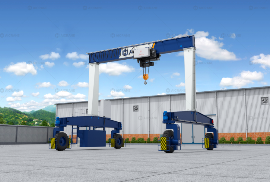
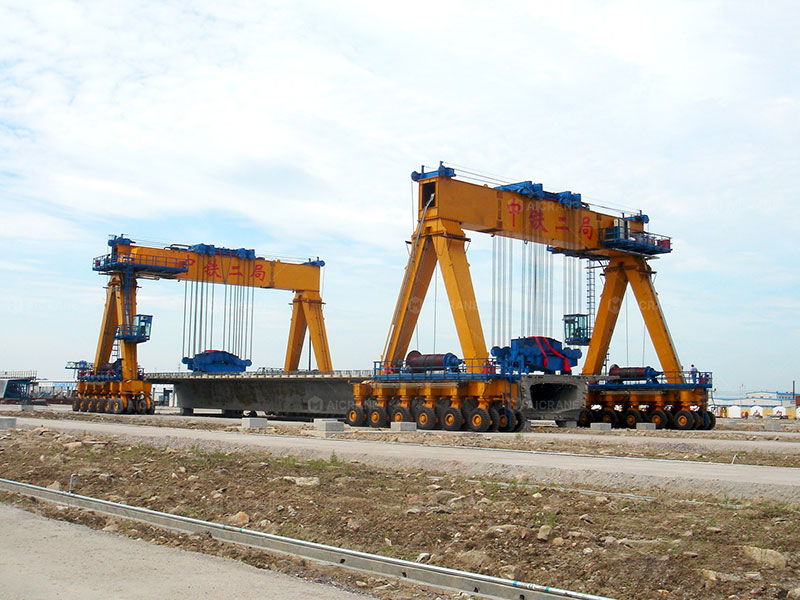
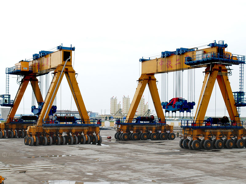
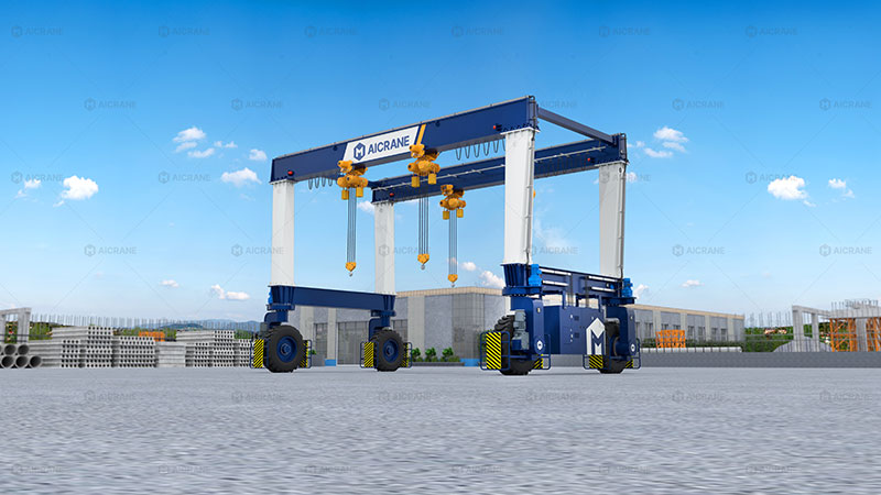
    Rubber Tyred Gantry (RTG) cranes have emerged as an effective technology for addressing these challenges. Unlike rail-mounted systems, RTG cranes combine high lifting capacity with mobility, allowing them to operate across wide yards without fixed foundations. This article explores the core technologies behind RTG rubber tyred gantry cranes and explains why they are particularly well suited for wind power and heavy equipment applications.

    RTG rubber tyred gantry crane

    Material Handling Challenges in Wind Power and Heavy Equipment Industries

    Wind power projects involve multiple stages of handling, from manufacturing and storage to transportation and installation preparation. Wind turbine blades can exceed 80 meters in length, tower sections weigh dozens of tons, and nacelles integrate sensitive mechanical and electrical systems. These components require precise, stable, and damage-free lifting.

    Heavy equipment manufacturing and assembly present similar challenges. Large structural components, engines, and modular assemblies must be moved between workstations, outdoor storage areas, and logistics zones. Frequent layout changes, varying load sizes, and tight project schedules demand lifting systems that are both powerful and adaptable.

    RTG crane technology addresses these challenges by providing high-capacity lifting, wide-area coverage, and flexible mobility, making it ideal for complex and evolving work environments.

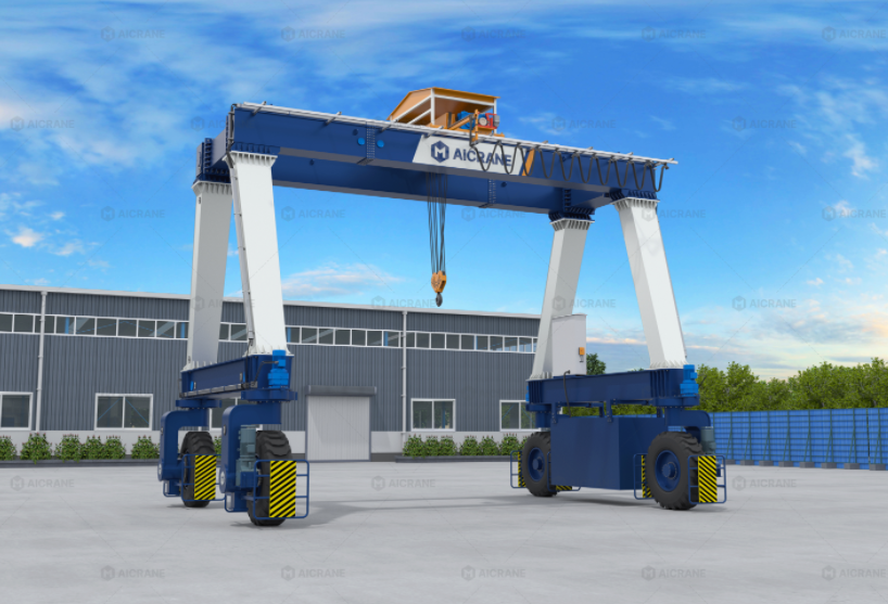
    Core Design Features of Rubber Tyred Gantry Cranes

    High-Capacity Structural Design

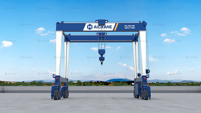
    RTG cranes used in wind power and heavy equipment applications are typically designed with reinforced box girder or hybrid truss structures. These designs offer high torsional stiffness and load-bearing capacity while maintaining structural stability during long-span operations.

    Advanced structural analysis, including finite element modeling, ensures that the crane can safely handle asymmetrical loads and dynamic forces common in wind turbine component lifting. The result is a robust crane structure capable of supporting loads ranging from tens to hundreds of tons.

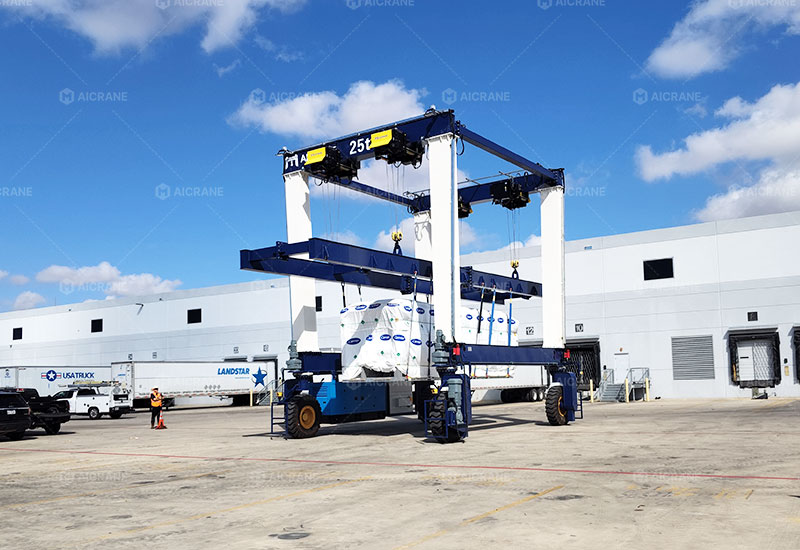
    Wide Span and Clearance Capabilities

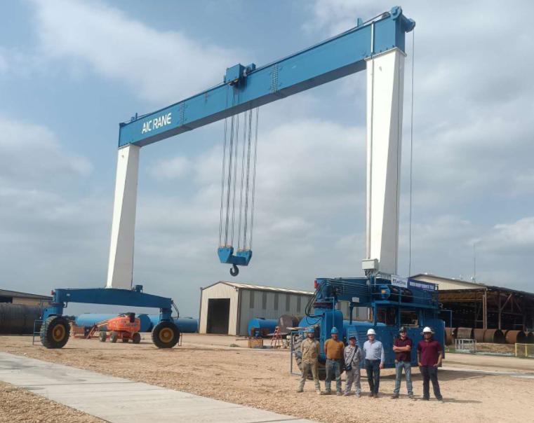
    Wind turbine components often require large clearance heights and wide spans. RTG cranes can be customized with extended spans and increased lifting heights to accommodate oversized components without the need for multiple lifting systems.

    The ability to straddle large loads and transport them across open yards is a key advantage of RTG technology in wind power logistics and heavy equipment assembly.

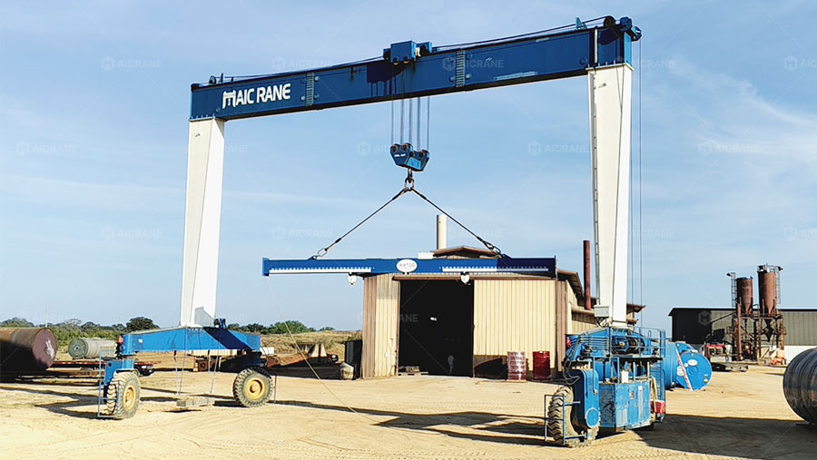
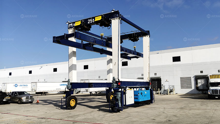
    Mobility and Steering Technology

    Rubber Tyre Travel System

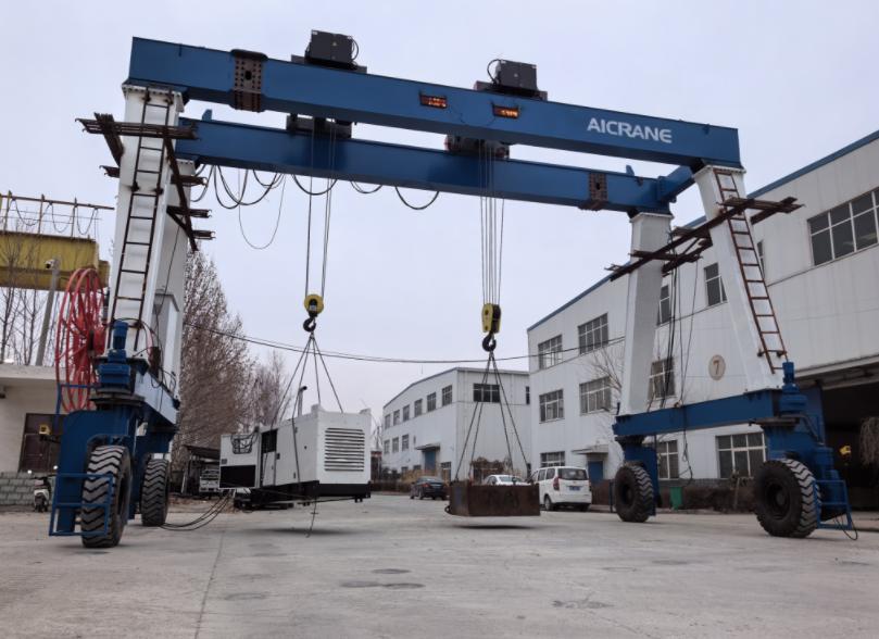
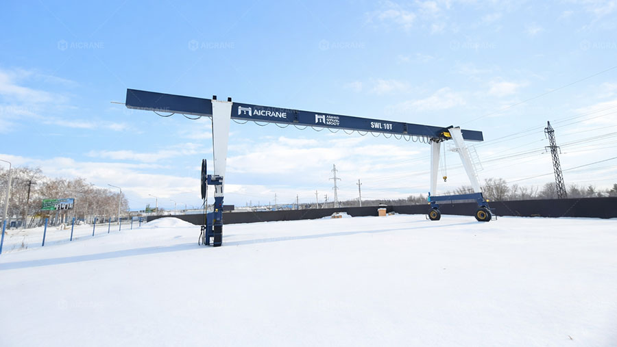
    The defining feature of RTG cranes is their rubber tyre travel system, which allows movement without rails or permanent foundations. This mobility is particularly valuable in wind power yards and heavy equipment facilities where layouts may change frequently as projects progress.

    RTG cranes distribute load across multiple wheels, reducing ground pressure and allowing operation on reinforced concrete, asphalt, or compacted gravel surfaces.

    Advanced Steering Modes

    Modern RTG cranes are equipped with multiple steering modes, including straight travel, diagonal movement, and pivot steering. These capabilities enable precise positioning of large components in confined spaces.

    For wind turbine blade handling, where alignment accuracy is critical, advanced steering technology ensures smooth and controlled mobile gantry crane movement, reducing the risk of component damage.

    RTG rubber tyred gantry cranes

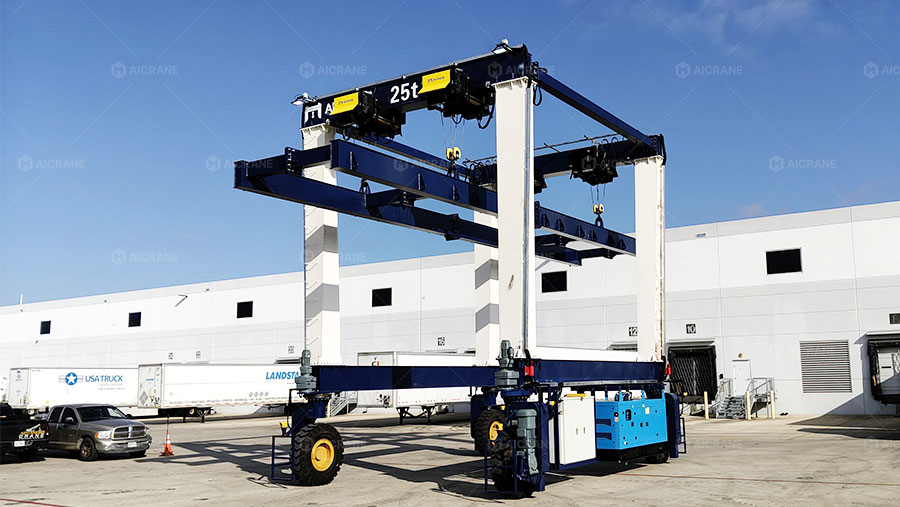
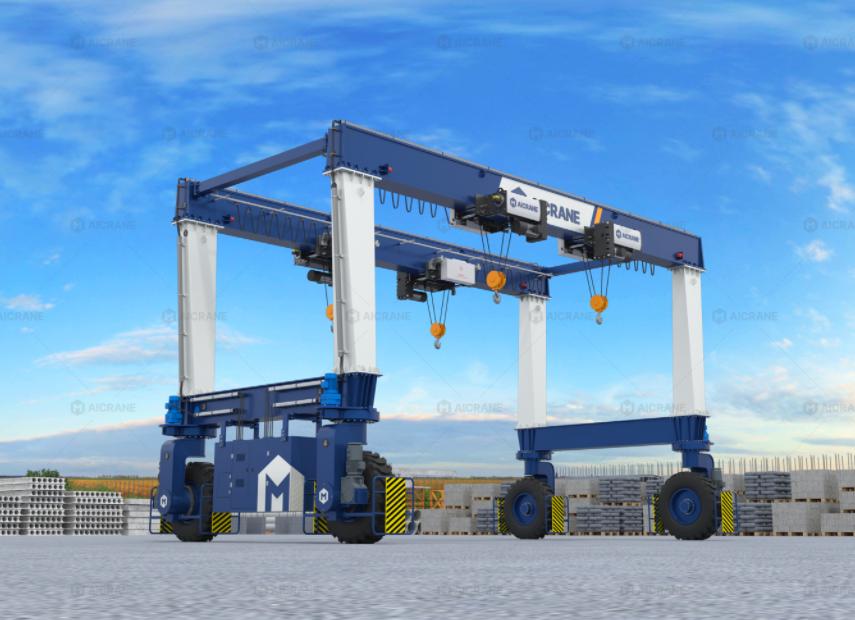
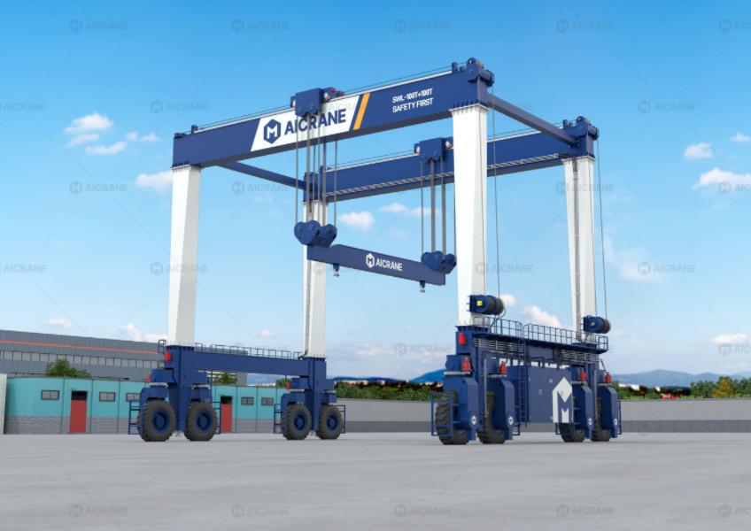
    Hoisting and Control Technology for Large and Sensitive Loads

    Precision Hoisting Systems

    RTG cranes for wind power and heavy equipment are equipped with high-performance hoisting mechanisms designed for smooth, controlled lifting. Variable frequency drives (VFDs) allow precise speed regulation, reducing shock loads during start and stop operations.

    Multi-hoist configurations can be used for synchronized lifting of long or flexible components, such as wind turbine blades, ensuring even load distribution and structural integrity.

    Intelligent Control Systems

    Modern RTG cranes integrate PLC-based control systems with advanced human-machine interfaces (HMIs). These systems provide real-time feedback on load weight, hoisting speed, and crane position.

    Control algorithms support functions such as load sway suppression, soft start and stop, and automatic positioning, all of which are essential when handling high-value and sensitive equipment.

    Safety Technology for Wind Power and Heavy Equipment Handling

    Safety is a critical consideration in both wind power and heavy equipment operations, where loads are heavy, large, and often handled outdoors.

    RTG cranes are equipped with comprehensive safety systems, including overload protection, emergency braking, and wind speed monitoring. Anti-sway technology minimizes load movement during lifting and travel, enhancing stability and operator confidence.

    Collision avoidance systems and zone protection technologies prevent crane movement into restricted areas or potential obstacles, improving overall site safety.

    Energy Efficiency and Sustainable Operation

    As renewable energy projects emphasize sustainability, the energy efficiency of handling equipment becomes increasingly important. RTG crane technology has evolved to support energy-efficient and environmentally responsible operation.

    Electric and hybrid RTG cranes reduce fuel consumption and emissions compared to traditional diesel-powered systems. Regenerative braking technology allows energy generated during lowering or braking to be recovered and reused.

    These features align RTG crane operations with the sustainability goals of wind power projects and heavy industry facilities.

    Integration with Digital and Smart Yard Systems

    IoT-Enabled Monitoring and Data Collection

    RTG cranes can be equipped with IoT sensors that monitor operational parameters such as load cycles, motor temperatures, and energy consumption. This data supports real-time monitoring and predictive maintenance strategies.

    In wind power logistics yards, IoT-enabled RTG cranes provide visibility into component movement and storage status, improving planning and coordination.

    Predictive Maintenance and Asset Management

    By analyzing operational data, maintenance teams can identify early signs of wear or misalignment and address issues before failures occur. Predictive maintenance reduces downtime and extends equipment lifespan, which is especially valuable in project-driven wind power operations with tight schedules.

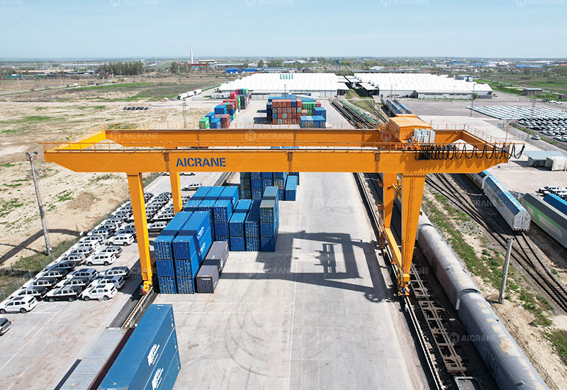
    Application Scenarios in Wind Power and Heavy Equipment

    RTG cranes are widely used in wind turbine manufacturing plants for handling blades, towers, and nacelles. They support outdoor storage and pre-assembly areas, where mobility and large coverage are essential.

    In heavy equipment manufacturing, RTG cranes facilitate the movement of large modules between fabrication, assembly, and testing areas. Their ability to adapt to changing layouts makes them suitable for project-based and custom manufacturing environments.

    RTG cranes are also used in logistics hubs for loading and unloading oversized equipment onto transport vehicles, streamlining the supply chain for large-scale projects.

    Challenges and Engineering Considerations

    While RTG cranes offer significant advantages, successful deployment requires careful consideration of ground conditions, wind loads, and operational requirements. Engineering assessments ensure that tyre selection, wheel load distribution, and braking systems are appropriate for site conditions.

    Operator training and maintenance planning are equally important to maximize the benefits of RTG crane technology.

    Future Trends in RTG Crane Technology

    The future of RTG crane technology for wind power and heavy equipment includes greater automation, enhanced digital integration, and increased use of clean energy. Advances in AI and machine learning will enable smarter control systems and autonomous operation in defined environments.

    As wind turbines continue to grow in size and complexity, RTG cranes will evolve to meet higher capacity and precision requirements, reinforcing their role as essential tools in the renewable energy and heavy equipment sectors.

    Conclusion

    Rubber tyred gantry crane technology offers a powerful and flexible solution for the demanding material handling requirements of wind power and heavy equipment industries. By combining high lifting capacity, mobility, advanced control systems, and intelligent safety features, RTG cranes enable efficient and safe handling of oversized and high-value components.

    As these industries continue to expand and modernize, RTG cranes will remain a key enabler of productivity, sustainability, and operational excellence.

  • Structural Design for Multi-Steering Rubber Tyred Gantry Cranes

    Rubber Tyred Gantry (RTG) cranes are a cornerstone of modern container terminals, precast yards, steel yards, and logistics hubs. As operational demands evolve toward higher flexibility, tighter yards, and complex material flow, multi-steering RTG cranes—capable of straight travel, diagonal movement, crab steering, and pivot steering—have become increasingly important.

    Behind this operational flexibility lies a highly demanding structural design challenge. Unlike conventional RTGs that mainly travel in straight lines, multi-steering RTGs introduce complex load paths, torsional stresses, and dynamic forces that must be carefully managed through advanced structural engineering.

    This article provides a comprehensive overview of the structural design principles, challenges, and solutions for multi-steering rubber tyred gantry cranes, focusing on safety, durability, and performance under diverse steering modes.

    RTG rubber tyred gantry crane

    1. Why Multi-Steering Changes Structural Design Fundamentals

    Traditional RTG cranes are primarily designed for longitudinal travel along container stacks. Loads are transferred vertically through the gantry legs to the wheels with relatively predictable stress distribution.

    Multi-steering RTGs, however, operate under non-linear movement patterns, including:

    • Diagonal travel for flexible yard alignment

    • Crab steering for lateral positioning without rotating the crane

    • Pivot or zero-radius steering for tight maneuvering

    • Combined steering modes under partial load conditions

    Each of these movements introduces horizontal forces, torsional moments, and asymmetric wheel loading, which significantly affect structural design.

    Key structural impacts include:

    • Increased torsion in the gantry frame

    • Uneven stress distribution between legs

    • Dynamic fatigue from frequent steering transitions

    • Higher demands on joint rigidity and structural continuity

    As a result, multi-steering RTG cranes require a more advanced and holistic structural design approach than conventional models.

    2. Overall Structural Layout of Multi-Steering RTGs

    2.1 Gantry Frame Configuration

    The core structure of an RTG crane consists of:

    • Main girders

    • End beams

    • Rigid or semi-rigid legs

    • Portal bracing systems

    For multi-steering RTGs, the gantry frame must balance global rigidity with controlled flexibility. Excessive stiffness may transfer high stress to local components, while insufficient stiffness can lead to deformation, misalignment, or fatigue cracking.

    Design priorities include:

    • High torsional stiffness of the main girder

    • Symmetrical load transfer paths

    • Minimized eccentric loading during steering

    Box-type welded girders are commonly adopted to enhance torsional resistance while keeping weight under control.

    RTG rubber tyred gantry cranes

    3. Structural Challenges Introduced by Multi-Steering Systems

    3.1 Torsional Loads During Crab and Diagonal Steering

    When an RTG moves sideways or diagonally, wheel forces no longer align with the crane’s longitudinal axis. This causes torsional moments around the vertical axis of the structure.

    Structural consequences include:

    • Twisting of the main girder

    • Differential displacement between legs

    • Increased stress at welded joints and connections

    To address this, designers must:

    • Increase torsional rigidity of girders

    • Optimize bracing geometry

    • Reinforce high-stress transition zones

    3.2 Asymmetric Wheel Load Distribution

    Multi-steering modes can lead to uneven wheel loading, especially during:

    • Turning under load

    • Acceleration and braking while steering

    • Operation on uneven ground

    Structural design must account for:

    • Higher localized stresses at wheel supports

    • Increased bending moments in legs and end beams

    • Dynamic amplification factors

    Finite Element Analysis (FEA) is essential to simulate these complex load scenarios and ensure structural integrity under worst-case conditions.

    4. Main Girder Structural Design

    4.1 Girder Cross-Section Optimization

    The main girder is the primary load-bearing component. For multi-steering RTGs, its design must satisfy:

    • Vertical bending from lifted loads

    • Horizontal bending from travel and steering

    • Torsional loading from crab and diagonal movement

    Closed box sections are preferred due to their superior torsional resistance compared to I-beam or open sections.

    Design considerations include:

    • Wall thickness optimization

    • Internal diaphragms to control warping

    • Smooth stress transitions to avoid fatigue concentration

    4.2 Fatigue-Resistant Design

    Multi-steering operation increases the number of load cycles and stress reversals. Structural fatigue becomes a critical design factor.

    Fatigue mitigation strategies include:

    • Continuous welds with smooth profiles

    • Avoidance of sharp geometric transitions

    • Reinforcement of high-cycle zones such as girder-leg junctions

    Compliance with international standards such as FEM, ISO, or EN fatigue classifications is essential.

    5. Gantry Legs and End Beam Design

    5.1 Leg Structure and Stability

    RTG legs serve as the main load transfer path to the wheels. In multi-steering mobile gantry cranes, legs must withstand:

    • Vertical compression

    • Horizontal shear forces

    • Bending and torsion during turning

    Design approaches include:

    • Box-type leg sections for multi-directional strength

    • Reinforced corner nodes at leg-girder connections

    • Increased safety margins against buckling

    5.2 End Beam and Wheel Support Design

    End beams experience complex loading due to:

    • Steering-induced lateral forces

    • Uneven wheel pressure

    • Dynamic braking loads

    Structural solutions include:

    • Reinforced wheel mounting plates

    • Stiffened end beam boxes

    • High-strength bolted or welded connections

    These measures ensure accurate wheel alignment and long-term operational stability.

    6. Structural Integration with Steering and Drive Systems

    6.1 Steering Mechanism Load Transfer

    Multi-steering RTGs rely on:

    • Hydraulic or electric steering actuators

    • Linkages integrated into wheel assemblies

    The crane structure must:

    • Provide rigid mounting points

    • Prevent local deformation under steering forces

    • Isolate vibration from sensitive components

    Reinforced brackets and localized structural thickening are commonly used in steering connection zones.

    6.2 Structural Accommodation for Control Precision

    High-precision steering requires:

    • Minimal structural deflection

    • Controlled elastic deformation

    Excessive flexing can lead to:

    • Steering lag

    • Uneven wheel angles

    • Increased tire wear

    Therefore, structural stiffness must be carefully matched to steering system responsiveness.

    7. Ground Conditions and Structural Adaptability

    Multi-steering RTGs often operate in:

    • Yards with uneven pavement

    • Temporary construction sites

    • Mixed surface conditions

    Structural design must account for:

    • Differential settlement

    • Wheel lift scenarios

    • Load redistribution during steering

    This is addressed through:

    • Increased structural redundancy

    • Conservative design load combinations

    • Enhanced safety factors

    8. Low-Temperature and Harsh Environment Considerations

    For RTGs operating in cold regions or harsh environments, structural design must also consider material performance.

    Key measures include:

    • Use of low-temperature structural steel (e.g., Q355E)

    • Enhanced fracture toughness

    • Crack propagation control

    These factors are particularly critical in multi-steering cranes due to higher dynamic stress levels.

    9. Role of Finite Element Analysis in Structural Design

    Modern multi-steering RTG design relies heavily on advanced simulation tools.

    FEA is used to:

    • Model complex steering load cases

    • Analyze torsional and fatigue behavior

    • Optimize material distribution

    Typical simulations include:

    • Straight travel under full load

    • Crab steering with offset load

    • Pivot turning under partial load

    • Emergency braking during diagonal movement

    Only through comprehensive simulation can designers ensure both safety and efficiency.

    10. Conclusion

    The structural design of multi-steering rubber tyred gantry cranes represents a significant evolution in crane engineering. As operational flexibility becomes a critical requirement in modern logistics and industrial yards, the structure must support complex movements without compromising safety, durability, or precision.

    Key takeaways include:

    • Multi-steering introduces complex torsional and dynamic loads

    • Structural rigidity and fatigue resistance are essential

    • Main girders, legs, and end beams require optimized box-type designs

    • Integration with steering systems must be structurally robust

    • Advanced FEA and conservative design principles are indispensable

    A well-designed multi-steering RTG crane structure not only enhances maneuverability but also ensures long service life, reduced maintenance, and reliable performance in demanding environments.

  • Gantry Crane Traveling Mechanism: Rail-Mounted vs Rubber Tyred

    Gantry cranes are essential lifting machines used in a wide range of industries, from shipyards and steel mills to precast concrete plants and logistics terminals. One of the most critical components determining a gantry crane’s operational efficiency is its traveling mechanism, which governs how the crane moves across the workspace. Broadly, gantry cranes can be classified based on their traveling system into rail-mounted gantry (RMG) cranes and rubber tyred gantry (RTG) cranes. While both types serve similar purposes—lifting and moving heavy loads—their traveling mechanisms, operational characteristics, and ideal applications differ significantly. Understanding these differences helps in selecting the right crane type for specific operational needs.

    1. Overview of Gantry Crane Traveling Mechanisms

    The traveling mechanism of a gantry crane consists of the components that allow the crane to move along a predefined path. This movement can be longitudinal along rails, or flexible over a yard using wheels and tires. The traveling system interacts closely with the hoisting and trolley mechanisms to ensure smooth load handling and precise positioning.

    The main objectives of a gantry crane’s traveling mechanism include:

    • Providing stable movement: Ensuring the crane moves smoothly under load without excessive sway or vibration.

    • Facilitating precision positioning: Allowing the operator to place loads accurately within the operational area.

    • Supporting heavy loads: The system must bear the weight of the crane structure and lifted materials.

    • Ensuring safety and reliability: The mechanism should minimize derailment risks, slipping, or tipping.

    2. Rail-Mounted Gantry (RMG) Crane Traveling Mechanism

    Rail-mounted gantry cranes are designed to move along fixed rails installed on the ground. These cranes are widely used in container terminals, steel plants, and industrial facilities where heavy, repetitive, and linear material handling is required.

    RMG container crane

    2.1 Structure and Components

    The traveling mechanism of an RMG crane typically consists of:

    • Wheel bogies: Mounted at the base of the crane legs, these wheels run on steel rails and carry the entire load of the crane.

    • Rails: Fixed tracks installed along the crane’s operational path, usually made of high-strength steel to support heavy loads and prevent wear.

    • Drive motors and gearboxes: Powered by electric motors, these components propel the crane along the rails. Gearboxes adjust the torque and speed for smooth movement.

    • Braking system: Ensures the crane can stop precisely and safely under full load conditions. Modern systems often use electro-mechanical brakes or hydraulic brakes.

    • Guidance systems: Maintain alignment on the rails and prevent lateral movement or derailment.

    2.2 Advantages of RMG Traveling Mechanisms

    1. High load capacity: RMG cranes are ideal for extremely heavy loads, with capacities often exceeding 100 tons, as the rails provide stable support.

    2. Precision movement: Rails ensure straight, predictable motion, which is critical when stacking containers, handling steel coils, or positioning precast components.

    3. Durability: Steel rails and robust wheel assemblies withstand harsh operational conditions and high-frequency operations over many years.

    4. Energy efficiency: Continuous rail contact reduces rolling resistance compared to tires, lowering energy consumption during movement.

    2.3 Limitations

    • Fixed travel path: The crane can only move where rails are installed, limiting operational flexibility.

    • High infrastructure cost: Rail installation, maintenance, and leveling require significant upfront investment.

    • Time-consuming relocation: Moving an RMG crane to a new location involves extensive civil works and rail adjustments.

    3. Rubber Tyred Gantry (RTG) Crane Traveling Mechanism

    Rubber tyred gantry cranes, on the other hand, move on large rubber tires rather than fixed rails. These cranes are often found in container yards, bulk material handling areas, and flexible logistics terminals where mobility across large areas is critical.

    RTG Crane

    3.1 Structure and Components

    The traveling mechanism of an RTG crane includes:

    • Rubber tires: Mounted on the crane legs, these tires support the crane’s weight and allow it to move over concrete pads or paved surfaces. Tires can be pneumatic or solid, depending on load and terrain requirements.

    • Steering system: Allows maneuvering and alignment of the crane, often with multiple steering modes including crab steering, synchronized turning, and diagonal movement.

    • Drive motors and transmission: Electric or hybrid systems power the wheels. Some modern RTGs feature independent wheel drives for enhanced maneuverability.

    • Stabilizers or leveling system: Ensures safe operation by maintaining crane balance when lifting uneven loads.

    • Guidance and monitoring: GPS, laser guidance, or sensors help operators maintain proper alignment with stacking rows or transport paths.

    3.2 Advantages of RTG Traveling Mechanisms

    1. High mobility: RTG gantry cranes can travel across large areas without fixed rails, making them ideal for expanding or changing yard layouts.

    2. Flexibility: They can access areas where rails cannot be installed, including temporary storage yards or uneven surfaces.

    3. Lower infrastructure cost: There is no need for rail tracks, reducing installation and civil engineering expenses.

    4. Multiple steering modes: Operators can adjust the crane’s movement to navigate tight spaces, avoid obstacles, or optimize stacking patterns.

    3.3 Limitations

    • Lower load capacity compared to RMGs: Rubber tires have limits on weight they can safely bear, especially for extremely heavy loads.

    • Surface dependency: Operation requires smooth, well-maintained concrete pads; rough or uneven surfaces can reduce stability.

    • Higher maintenance: Tires wear faster than steel wheels, and steering systems require frequent checks and adjustments.

    • Energy consumption: Rolling resistance of rubber tires is higher, which can lead to increased energy use for frequent or long-distance travel.

    4. Key Differences Between RMG and RTG Traveling Mechanisms

    Feature Rail-Mounted Gantry (RMG) Rubber Tyred Gantry (RTG)
    Travel path Fixed rails Free on flat surfaces
    Load capacity Very high (up to 1,000+ tons for heavy industrial applications) Moderate to high (usually below 150 tons for standard designs)
    Mobility Limited Flexible and highly maneuverable
    Installation cost High (rails, leveling, foundation) Lower (paved pads suffice)
    Maintenance Lower rolling wear; less frequent inspections Higher tire wear; steering and alignment require regular checks
    Precision Excellent linear accuracy Moderate; relies on guidance systems for positioning
    Energy efficiency Higher due to low rolling resistance Lower due to tire friction
    Ideal applications Container terminals with fixed lanes, steel mills, precast plants Flexible container yards, bulk material handling areas, temporary storage sites

    5. Applications and Considerations

    When selecting between RMG and RTG traveling mechanisms, several operational factors must be considered:

    1. Load requirements: For ultra-heavy lifting and stacking of standardized materials, RMG cranes are preferable. RTG cranes suit medium to heavy loads where operational flexibility is essential.

    2. Operational area: If the crane must cover a large, adjustable yard or travel between multiple storage zones, RTG cranes are ideal. For long, narrow operational lanes, RMG cranes are more efficient.

    3. Infrastructure investment: Rail-mounted systems require more civil engineering upfront, while RTG cranes can operate on existing concrete pads with minimal preparation.

    4. Maintenance capacity: Facilities with robust maintenance teams may manage RTG tire wear and steering upkeep effectively. Otherwise, the low-maintenance nature of RMG cranes can be a decisive factor.

    5. Environmental and surface conditions: RMG cranes tolerate minor ground imperfections if rails are properly leveled. RTG cranes require high-quality surfaces to maintain stability under load.

    6. Future Trends in Gantry Crane Traveling Mechanisms

    Modern gantry crane designs increasingly integrate automation, sensors, and digital monitoring into traveling mechanisms. Both RMG and RTG cranes now feature:

    • Automated movement systems: GPS-guided or PLC-controlled travel for precise load placement.

    • Energy recovery systems: Regenerative braking reduces power consumption.

    • Condition monitoring: Sensors track wheel, motor, and steering wear to predict maintenance needs.

    • Hybrid power options: Especially for RTG cranes, combining diesel and electric drives improves efficiency and reduces emissions.

    The choice between rail-mounted and rubber-tyred systems is also evolving. Some facilities adopt hybrid solutions, using RMG cranes on fixed lanes for heavy loads while RTG cranes handle flexible, temporary storage areas, achieving both precision and adaptability.

    Conclusion

    The traveling mechanism is a cornerstone of gantry crane performance, influencing load capacity, operational flexibility, maintenance requirements, and overall productivity. Rail-mounted gantry (RMG) cranes excel in high-capacity, precise, and linear operations, making them ideal for container terminals, steel mills, and industrial production lines. Rubber tyred gantry (RTG) cranes, with their mobility and flexible steering options, suit dynamic yard environments where layout adjustments or multi-directional access is required.

    Selecting the appropriate traveling mechanism requires a comprehensive understanding of load requirements, operational area, infrastructure investment, and maintenance capabilities. As gantry crane technology continues to evolve, integrating digital monitoring, automation, and hybrid mobility systems will further enhance the efficiency and versatility of both RMG and RTG cranes, ensuring that these essential machines remain at the heart of modern material handling operations.

  • Electrical System Safety Requirements for Rubber Tired Gantry Cranes

    Rubber Tired Gantry (RTG) cranes are widely used in container terminals, logistics yards, and industrial facilities due to their flexibility, mobility, and high productivity. As RTG cranes become more technologically advanced—with electric drives, PLC control, smart anti-collision systems, and energy-saving technologies—the electrical system plays an increasingly critical role in safe and reliable crane operation.

    Because RTGs operate outdoors, handle heavy loads, and are frequently exposed to harsh environmental conditions, electrical system safety must be addressed with rigorous standards. Poor electrical design or insufficient protection can lead to operational breakdowns, fire hazards, personnel injury, and costly downtime. This article explains the key electrical system safety requirements for RTG cranes and how they ensure stable performance in demanding container-handling environments.

    rubber tired gantry crane

    1. Overview of Electrical Systems in RTG Cranes

    Modern rubber tired gantry crane for sale typically uses the following electrical configurations:

    • Diesel-electric RTG cranes: Diesel generator powers electric motors and systems.

    • Hybrid RTG cranes: Combine diesel power with energy storage systems such as batteries or ultracapacitors.

    • Full-electric RTG cranes: Powered by cable reel or busbar systems, achieving zero emissions.

    Regardless of the power source, all RTG cranes require highly reliable electrical components, including:

    • Main power distribution system

    • PLC controls and communication networks

    • Variable frequency drives (VFDs) for hoist, trolley, and gantry motors

    • Sensors, limit switches, overload protections

    • Emergency stops and grounding devices

    • Lighting, alarms, and auxiliary electrical devices

    Because all crane motions depend on these systems, ensuring their safety is essential for preventing accidents and ensuring operational continuity.

    2. Electrical Safety Standards and Compliance

    To guarantee safe use, RTG cranes must comply with major international standards such as:

    • IEC standards for electrical equipment

    • ISO 4306/4308 for crane safety

    • EN standards for hoist and lifting machinery

    • NFPA 70 (NEC) for electrical installations

    • IEEE standards for grounding and power systems

    Compliance helps ensure that electrical components can withstand high loads, heavy usage, vibration, and outdoor operation.

    3. Proper Electrical Insulation and Enclosures

    RTG cranes operate in unpredictable environments—rain, humidity, dust, salt air, and heat. Therefore, electrical enclosures must have:

    • Appropriate IP protection rating, usually IP55–IP65, to prevent water and dust penetration

    • High-quality insulation material for all cables, connectors, and terminals

    • Heat-resistant components inside control cabinets

    • Corrosion-resistant housings for marine or coastal areas

    Without these protections, moisture or dust can cause short circuits, motor failures, or unpredictable motion.

    4. Overcurrent, Overvoltage, and Short-Circuit Protection

    Electrical system safety is deeply dependent on reliable protection devices, including:

    Circuit breakers and fuses

    These protect against short circuits, electrical faults, and excessive current draw.

    Surge protection devices (SPDs)

    RTG cranes often operate in open areas and can be exposed to lightning strikes. SPDs protect sensitive electronics and VFDs from sudden voltage spikes.

    Soft starters or VFD protections

    Overvoltage, undervoltage, and overload protections are necessary to prevent damage to motors and drives.

    A failure in any of these protective components can lead to severe system failure or fire hazards.

    rubber tired gantry

    5. Grounding and Earthing Requirements

    Grounding is one of the most important electrical system safety concerns, especially on large steel structures like RTG cranes.

    Key grounding safety measures include:

    • Dedicated crane grounding system with low resistance

    • Earthing of all control panels, motors, and metal structures

    • Protection against static electricity buildup

    • Grounding for lightning protection systems

    Proper grounding ensures that leakage current is safely discharged and reduces electrocution risk for operators and maintenance personnel.

    6. Cable Management and Power Supply Safety

    RTG cranes have many moving parts, such as gantry wheels, trolley mechanisms, and hoist systems. Mismanaged cables can quickly become a safety hazard.

    Cable safety requirements include:

    • High-flexibility, wear-resistant cables for repeated movement

    • Cable trays and conduits to protect wiring from mechanical damage

    • Clear separation between power cables and control cables

    • Anti-abrasion and flame-retardant protection

    • Sufficient cable slack to avoid tension during crane motions

    For electric or hybrid RTG cranes, cable reel systems or busbar systems must be equipped with:

    • Emergency disconnect switches

    • Cable tension monitoring

    • Overwind protection

    • Mechanical guards to prevent crushing

    Proper cable design prevents short circuits, communication failures, and fire hazards.

    7. Motor and Drive Safety Protections

    RTG cranes use large electric motors for hoisting, cross-travel, and gantry travel. Motor safety measures include:

    Thermal overload protection

    Prevents overheating during prolonged operations.

    Brake monitoring sensors

    Ensures hoist motors can safely hold loads.

    Motor temperature sensors

    Detect early signs of motor deterioration.

    Drive system protections (VFD protections):

    • Overcurrent

    • Overvoltage/undervoltage

    • Phase loss and imbalance

    • Ground fault detection

    Drives must also be housed in climate-controlled cabinets to prevent heat buildup.

    8. PLC Control System Safety

    Modern RTG cranes rely on PLC-based automation for safety and motion coordination.

    Safety requirements include:

    • Redundant PLC architecture to prevent system failure

    • Fail-safe programming for emergency conditions

    • Closed-loop monitoring of crane motions

    • Backup communication channels

    Critical controls—hoisting, trolley movement, anti-sway systems—must have reliable feedback from encoders, limit switches, and sensors.

    PLC failures can lead to uncontrolled crane movement, so redundancy and protection are essential.

    9. Emergency Stop and Safety Interlocks

    Emergency systems must be accessible and highly reliable. RTG cranes must include:

    • Multiple emergency stop (E-stop) buttons around the movable gantry crane

    • Safety interlocks for hoist limit switches and travel limits

    • Overload protection devices

    • Anti-collision systems for gantry and trolley travel

    • Automatic power cutoff during critical faults

    These safety mechanisms ensure fast response during unexpected events and prevent severe accidents.

    10. Operator Cabin and Control Station Electrical Safety

    If the RTG crane is equipped with a cabin, the following requirements apply:

    • Insulated flooring to reduce shock risk

    • Flame-retardant wiring

    • Climate control to protect electronics

    • Surge-protected operator consoles

    • Clearly labeled control switches and displays

    • Redundant communication systems

    Wireless remote control RTGs also need secure communication encryption and interference protection.

    11. Regular Maintenance and Inspection

    Electrical safety is not achieved by design alone—it requires consistent maintenance, including:

    • Inspection of cables, connectors, and terminals

    • Thermal imaging to detect hot spots

    • Testing of grounding systems

    • Verification of limit switches and sensors

    • Cleaning of electrical cabinets

    • Replacement of worn-out parts

    A structured preventive maintenance program significantly increases crane safety and lifespan.

    Conclusion

    The electrical system of a Rubber Tired Gantry crane is the backbone of its operation and safety performance. From proper insulation and grounding to PLC redundancy, emergency systems, and cable protection, each component plays a vital role in preventing failures and accidents in demanding port and yard environments.

    By following international safety standards, incorporating robust protective devices, and implementing regular inspection routines, operators and owners can ensure their RTG cranes work efficiently, safely, and reliably for many years.

  • Electrical vs. Hydraulic Working Systems in Rubber Tyred Gantry Cranes

    Rubber Tyred Gantry (RTG) cranes are among the most essential pieces of equipment in container terminals, intermodal yards, and industrial storage areas. Their mobility, flexibility, and capacity to handle containers or heavy loads efficiently make them indispensable in modern logistics. The performance and efficiency of an RTG crane largely depend on its working system—specifically, whether it is electrically or hydraulically powered. Each system offers distinct advantages and trade-offs in terms of energy efficiency, control precision, maintenance, and cost.

    This article explores the major differences between electrical and hydraulic working systems in rubber tire gantry cranes, examining their structure, performance characteristics, environmental impact, and suitability for different applications.

    electric rubber tyred gantry crane

    Overview of Rubber Tyred Gantry Cranes

    Rubber Tyred Gantry cranes are mobile gantry cranes that run on pneumatic rubber tires instead of fixed rails. They are designed to straddle rows of containers or heavy materials, allowing for flexible movement and stacking operations within container yards, factories, and logistics hubs.

    An RTG crane consists of several key components:

    • Main structure: The gantry frame supported by rubber tires.

    • Lifting system: The hoist mechanism, trolley, and spreader or hook.

    • Travel system: The rubber tires powered by motors for horizontal movement.

    • Power system: Either electrical or hydraulic, responsible for operating the crane’s various motions—hoisting, trolley travel, gantry movement, and steering.

    The choice between electrical and hydraulic systems influences how these motions are powered and controlled, directly affecting the crane’s overall performance.

    Electrical Working System

    The electrical system in an RTG crane uses electric motors and drives to power all crane functions. Traditionally, RTGs relied on diesel generators for electricity, but modern systems increasingly adopt diesel-electric hybrids or fully electric power supplied through cable reels or busbar systems.

    Key Features

    • Electric motors: Used to drive the hoist, trolley, and gantry motions.

    • Variable Frequency Drives (VFDs): Control the speed and torque of motors for smooth and efficient operation.

    • Power supply: Can be onboard (via diesel generator) or external (through electric grid or battery).

    • Control system: Usually PLC-based, ensuring precise coordination of movements.

    Advantages of Electrical Systems

    1. Energy Efficiency
      Electrical RTGs typically consume less energy than hydraulic ones. With VFD technology, power consumption is optimized during acceleration and braking, and regenerative energy can even be recovered during load lowering.

    2. Low Operating Costs
      The use of electric motors reduces fuel usage, especially in fully electric or hybrid RTGs. Over time, this significantly lowers operational costs and dependency on fossil fuels.

    3. Environmental Sustainability
      Electric RTGs produce fewer emissions, making them compliant with global environmental regulations and suitable for ports aiming to reduce carbon footprints.

    4. Precise Control
      Electric drives offer superior precision in load control, allowing smoother lifting and lowering operations. This improves safety and reduces wear on mechanical components.

    5. Reduced Noise Levels
      Electric systems operate more quietly compared to hydraulic pumps, enhancing the working environment for operators and nearby personnel.

    Limitations of Electrical Systems

    • Higher Initial Cost: Fully electric RTGs require more expensive equipment and installation, including power infrastructure.

    • Limited Mobility (for grid-connected systems): If powered by cable reels or busbars, the crane’s movement area may be constrained.

    • Battery Maintenance (for hybrid systems): Battery-based systems require regular monitoring and replacement after several years.

    Hydraulic Working System

    In a hydraulic RTG crane, mechanical motions are powered by hydraulic pumps, which convert mechanical energy (usually from a diesel engine) into fluid power. Hydraulic actuators or cylinders then drive the lifting and movement functions.

    hydraulic rubber tyred gantry crane

    Key Features

    • Hydraulic pumps and cylinders: Provide force to hoist, move trolleys, or steer the wheeled gantry crane.

    • Fluid control valves: Regulate pressure and flow to achieve desired motion.

    • Diesel engine: Typically powers the hydraulic pump, though hybrid models may use electric motors.

    Advantages of Hydraulic Systems

    1. High Power Density
      Hydraulic systems are known for delivering strong power within compact components, making them ideal for heavy lifting applications where high torque is required.

    2. Smooth and Continuous Force
      Hydraulic cylinders provide steady and continuous movement, which can be beneficial in precise lifting or when handling uneven loads.

    3. Durability and Robustness
      Hydraulic components are rugged and can withstand harsh environmental conditions, including extreme temperatures or dusty outdoor operations.

    4. Simple Mechanical Structure
      Compared to electrical drives, hydraulic systems often have fewer electronic components, making them simpler to repair in remote or less technologically developed areas.

    Limitations of Hydraulic Systems

    • Energy Inefficiency: Hydraulic systems experience energy losses due to fluid friction and heat generation. This leads to higher fuel consumption compared to electric systems.

    • Maintenance Complexity: Hydraulic fluid leaks, pump wear, and seal replacements are common issues, requiring skilled technicians for upkeep.

    • Environmental Concerns: Hydraulic oil leaks pose environmental hazards, particularly in port areas where contamination can be costly.

    • Noise and Vibration: Hydraulic pumps generate more noise and vibration during operation, affecting operator comfort.

    Comparison Between Electrical and Hydraulic RTG Systems

    Criteria Electrical System Hydraulic System
    Power Source Electric motors (diesel-electric, grid, or battery) Diesel engine with hydraulic pumps
    Energy Efficiency High (with regenerative braking) Moderate (energy loss through fluid)
    Environmental Impact Low emissions and noise Higher emissions and potential oil leaks
    Control Precision Excellent with VFDs and PLCs Good but less precise
    Maintenance Easier, less frequent Requires regular oil checks and seal maintenance
    Initial Cost Higher Lower
    Mobility May be limited if grid-powered Fully mobile with diesel engine
    Power Density Moderate High
    Noise Level Low High

    Choosing the Right System for Your Application

    The decision between an electrical or hydraulic working system depends on the operational environment, budget, and sustainability goals.

    • Choose Electrical RTG Cranes If:

      • Energy efficiency and emission reduction are top priorities.

      • Your facility has reliable access to electric power infrastructure.

      • You aim to comply with environmental regulations or green port initiatives.

      • Precision and operator comfort are key considerations.

    • Choose Hydraulic RTG Cranes If:

      • You operate in remote areas without stable electric power supply.

      • Heavy-duty lifting with high torque is frequently required.

      • Maintenance personnel are familiar with hydraulic systems.

      • Initial investment cost is a limiting factor.

    Many modern ports are transitioning from hydraulic to hybrid or fully electric RTG cranes, recognizing the long-term benefits of energy efficiency, reduced maintenance, and sustainability. However, hydraulic cranes still hold a significant place in industries where ruggedness and mobility are paramount.

    The Future: Hybrid and Electric RTG Evolution

    The future of RTG crane technology lies in hybrid and fully electric designs. Hybrid RTGs use energy storage systems—such as batteries or ultracapacitors—to recover energy from braking and lowering operations. This reduces fuel consumption by up to 60% compared to conventional hydraulic RTGs.

    Fully electric RTGs, powered through cables or busbars, eliminate diesel engines entirely. These systems not only reduce emissions but also improve reliability by removing hydraulic components prone to leakage and maintenance.

    As global ports move toward carbon neutrality, the adoption of electric and hybrid RTG cranes is accelerating. Manufacturers are continuously improving motor efficiency, battery lifespan, and control systems to make electric solutions more practical and cost-effective for large-scale terminal operations.

    Conclusion

    Both electrical and hydraulic working systems play crucial roles in the operation of rubber tyred gantry cranes. Hydraulic systems offer strength, simplicity, and durability, making them ideal for heavy-duty and remote applications. Electrical systems, on the other hand, deliver superior efficiency, precision, and environmental performance—qualities that align with the future of sustainable port and industrial operations.

    Ultimately, the right choice depends on a careful assessment of operational needs, infrastructure, and long-term goals. As the industry continues to embrace cleaner technologies, electrification represents the next major leap in RTG crane innovation, setting a new standard for efficiency, reliability, and sustainability in material handling.

  • The Role of Suspension Systems in Rubber Tyred Gantry Cranes

    Rubber Tyred Gantry (RTG) cranes have become an indispensable part of modern port operations, container terminals, and large industrial yards. Their flexibility, mobility, and capacity to handle heavy loads make them essential equipment in moving containers, large molds, and other heavy cargo. While their lifting capabilities, steering mechanisms, and structural integrity often receive the most attention, the suspension system of an RTG crane is equally crucial. It plays a central role in operational stability, load handling efficiency, and overall safety. Understanding the function and significance of the suspension system helps operators, engineers, and logistics managers make informed decisions regarding maintenance, design, and crane selection.

    rubber tyred gantry crane

    Understanding the RTG Crane Suspension System

    An RTG crane typically consists of a span supported by two or more rubber-tyred legs, a hoist system, and a complex steering and drive system. Unlike rail-mounted gantry cranes, rubber tyre gantry cranes rely on their tires for mobility, which introduces unique challenges related to weight distribution, stability, and ground contact. The suspension system is designed to mitigate these challenges by ensuring that the crane maintains even weight distribution across all tires, absorbs shocks from uneven surfaces, and maintains consistent ground contact.

    In essence, the suspension system in an RTG crane serves several key purposes:

    1. Load Distribution and Stability:
      When an RTG crane lifts heavy containers or cargo, the load is transferred from the hoist to the crane’s structure and ultimately to the tires. Without a proper suspension system, the weight may be unevenly distributed, causing excessive stress on certain tires or crane legs. Unequal load distribution can lead to instability, wheel slippage, or even tipping in extreme cases. The suspension system ensures that each tire carries its share of the load, maintaining the crane’s balance and operational safety.

    2. Shock Absorption and Smooth Movement:
      RTG cranes operate on both paved surfaces and terminal ground, which may have minor unevenness or bumps. A robust suspension system absorbs these shocks, reducing vibrations transmitted to the crane structure and the load being carried. This not only enhances operator comfort but also minimizes stress on structural components, reducing wear and tear over time.

    3. Traction and Mobility Enhancement:
      Since RTG cranes rely on rubber tires rather than rails, maintaining consistent traction is critical. The suspension system ensures that all tires remain in contact with the ground, even on slightly uneven terrain. By maximizing tire contact, the crane can maneuver efficiently, navigate curves, and safely lift loads without compromising stability.

    4. Reduction of Structural Stress:
      Lifting and moving heavy containers generate significant dynamic forces that impact the crane’s girder, legs, and frame. A suspension system helps distribute these forces more evenly across the structure, reducing localized stress points that could lead to cracks, deformation, or mechanical failures. Over time, this contributes to the crane’s longevity and reduces the need for frequent maintenance.

    rtg cranes

    Types of Suspension Systems in RTG Cranes

    RTG cranes may incorporate several types of suspension systems depending on the manufacturer, crane design, and operational requirements. Common types include:

    1. Leaf Spring Suspension:
      Leaf springs are a traditional suspension solution in heavy machinery. In RTG cranes, they provide a simple yet effective method for absorbing shocks and maintaining load balance. While leaf springs are durable and capable of handling substantial loads, they may require periodic adjustments to maintain optimal performance.

    2. Hydraulic Suspension:
      Hydraulic suspension systems use pressurized fluid to adjust the height and damping characteristics of the crane’s legs. This type of suspension offers precise control over load distribution and can automatically adjust for uneven ground, making it ideal for high-capacity RTG straddle cranes operating on variable terrain. Hydraulic suspension also reduces vibration and improves operator comfort, especially during long operational hours.

    3. Air Suspension:
      Air suspension systems use compressed air in flexible bellows to support the crane’s weight and absorb shocks. This system provides excellent load leveling, smooth movement, and can adapt dynamically to changing loads or ground conditions. Air suspension is particularly beneficial in environments where ground surfaces are irregular or where load sensitivity is critical, such as handling delicate cargo or high-value containers.

    4. Combination Systems:
      Some modern RTG cranes incorporate hybrid suspension systems, combining hydraulic and air components to leverage the advantages of both technologies. These systems can optimize stability, comfort, and load handling in real-time, adapting to operational conditions and load characteristics.

    Impact of Suspension on Operational Efficiency

    The suspension system directly influences the operational efficiency of RTG cranes in several ways:

    • Improved Lifting Precision: A stable crane platform reduces sway and minimizes oscillations during lifting, which is especially important when stacking containers in high bays or working in confined spaces.

    • Enhanced Speed and Mobility: By maintaining tire contact and traction, the suspension system enables smoother movement, reducing the time required to transport containers across a terminal.

    • Reduced Maintenance Costs: A well-designed suspension system decreases stress on tires, axles, and structural components, resulting in longer service intervals and lower maintenance costs.

    • Operator Comfort and Safety: Shock absorption reduces fatigue for crane operators, leading to fewer operational errors and a safer working environment.

    Challenges and Considerations

    While suspension systems are crucial, they also present challenges that must be addressed:

    • Maintenance Requirements: Hydraulic and air suspension systems require regular inspections to ensure fluid levels, pressure, and leak-free operation. Neglect can lead to uneven load distribution or system failure.

    • Cost Implications: Advanced suspension systems, such as hydraulic or air suspension, increase the initial cost of the crane. However, this investment is often offset by enhanced operational efficiency and reduced maintenance costs.

    • Environmental Factors: RTG cranes operate outdoors and may be exposed to extreme temperatures, moisture, or saltwater environments. Suspension components must be designed to resist corrosion and perform reliably under varying conditions.

    Future Trends in RTG Crane Suspension

    The demand for higher-capacity RTG cranes and smarter port operations is driving innovations in suspension technology:

    1. Intelligent Suspension Systems: Integration of sensors and automated control systems allows real-time adjustment of suspension characteristics based on load weight, speed, and terrain conditions. This increases safety and efficiency while reducing operator workload.

    2. Predictive Maintenance: Advanced suspension systems can be equipped with diagnostic tools to monitor wear, pressure, and performance. This enables predictive maintenance, reducing unexpected downtime and extending the lifespan of critical components.

    3. Energy Efficiency: Optimized suspension reduces energy consumption by minimizing rolling resistance and vibration losses during crane movement. This aligns with growing sustainability goals in ports and industrial operations.

    Conclusion

    The suspension system of a Rubber Tyred Gantry crane is far more than a comfort feature – it is a critical component that ensures operational stability, safety, and efficiency. By evenly distributing loads, absorbing shocks, enhancing traction, and reducing structural stress, the suspension system allows RTG cranes to perform demanding lifting and transport tasks reliably. Advances in hydraulic, air, and intelligent suspension systems continue to improve the performance of RTG cranes, making them safer, more efficient, and better suited to modern port and industrial environments.

    For operators and engineers, understanding the role and design of suspension systems is essential in optimizing crane performance, reducing maintenance costs, and ensuring safe and efficient material handling operations. Whether deploying a small RTG crane in a container yard or a large high-capacity crane in a global port, the suspension system is an unsung hero that supports every lift, movement, and operation.

  • How to Handle Emergency Situations with Rubber Tyred Gantry Cranes

    Rubber Tyred Gantry (RTG) cranes are critical assets in container terminals, intermodal yards, and logistics hubs, designed to efficiently lift and transport containers across large working areas. However, like any heavy equipment, RTG cranes can face unexpected emergency situations ranging from equipment malfunctions to environmental hazards and operational accidents. Properly handling these emergencies is vital to protect personnel, cargo, and equipment while ensuring continuity of operations. This article explores common emergency scenarios, outlines best practices for response, and highlights the importance of training, planning, and technology in minimizing risks.

    rubber tyred gantry crane

    Common Emergency Situations in RTG Crane Operation

    Before discussing response strategies, it’s important to understand the types of emergencies that can arise in RTG crane operations:

    1. Power Failures – RTGs may experience sudden loss of electrical power due to grid failure, generator malfunction, or fuel shortages in hybrid models.

    2. Mechanical Failures – Issues such as hoist brake malfunction, trolley derailment, or gantry drive failure can suddenly stop operations and compromise safety.

    3. Electrical Malfunctions – Short circuits, control system errors, or PLC (Programmable Logic Controller) failures can render the tyre mounted gantry crane inoperable.

    4. Load Emergencies – Overloaded containers, dropped loads, or swinging loads due to operator error or strong winds.

    5. Weather-related Hazards – High winds, lightning, heavy rain, or earthquakes can put cranes and operators at risk.

    6. Fire Emergencies – Fires can occur due to overheating electrical systems, fuel leaks in diesel generators, or hydraulic oil ignition.

    7. Operator or Personnel Injury – Accidents involving crane operators or ground personnel during lifting or container positioning.

    Understanding these possible scenarios allows terminal operators to prepare structured emergency plans.

    Emergency Preparedness: The First Line of Defense

    Preparation is the key to minimizing risks during emergencies. Every port or container yard operating RTG cranes should have a documented Emergency Response Plan (ERP) that outlines step-by-step actions in various crisis situations. Key elements of preparedness include:

    • Training and Drills: Operators and ground staff must be trained in emergency shutdown, evacuation, and communication protocols. Regular drills help maintain readiness.

    • Clear Communication Channels: Two-way radios or digital communication systems must be available to instantly alert supervisors and emergency response teams.

    • Accessible Emergency Equipment: Fire extinguishers, spill kits, first aid stations, and emergency power backup should be strategically located around the yard.

    • Signage and Markings: Emergency stop buttons, escape routes, and safe assembly points should be clearly marked.

    Step-by-Step Response to Key Emergency Situations

    1. Power Failures

    In case of a power outage, the operator should:

    • Immediately activate the emergency brake systems to secure the load.

    • Communicate with the control room to notify of the power failure.

    • Avoid attempting to move the crane until backup power or repairs are provided.

    • If the crane is equipped with a diesel generator or hybrid system, switch to alternative power supply following proper procedures.

    2. Mechanical or Electrical Failures

    When mechanical or electrical issues occur:

    • Operators must stop all crane movement immediately using the emergency stop (E-stop) function.

    • Secure the load in its current safe position if possible.

    • Report the malfunction to the maintenance team without attempting makeshift repairs.

    • Evacuate the operator cabin if the situation poses a risk of collapse, fire, or electrical hazard.

    3. Load Emergencies

    Load-related emergencies are particularly dangerous:

    • If a load begins to sway uncontrollably, the operator should avoid sudden braking or acceleration, instead allowing controlled stabilization.

    • In case of overload detection, modern RTGs are equipped with overload limiters that automatically halt hoisting; operators must follow protocols to lower the load safely once systems allow.

    • If a container slips or falls, halt operations immediately, secure the site, and provide first aid or emergency response if personnel are affected.

    RTG crane

    4. Weather Hazards

    RTGs are highly vulnerable to weather conditions:

    • During high winds, operators should lower containers to the ground and park the movable gantry crane in a designated safe area with storm locks engaged.

    • In case of lightning storms, operators should stop work and seek shelter away from the crane, as cranes can act as lightning conductors.

    • In earthquakes, operators should stop the crane, lower the load if possible, and evacuate to a safe zone.

    5. Fire Emergencies

    A fire in an RTG crane can spread quickly due to hydraulic oil or fuel:

    • Operators should immediately hit the emergency stop button and evacuate the cabin.

    • Use fire extinguishers if the fire is small and manageable; otherwise, wait for professional responders.

    • Shut down nearby cranes or equipment to prevent the fire from spreading.

    • Report the incident to fire response teams and supervisors.

    6. Personnel Accidents

    If an operator or ground worker is injured:

    • Stop all crane operations immediately.

    • Secure the area to prevent additional injuries.

    • Provide first aid and call medical responders without delay.

    • File an incident report and review procedures to prevent recurrence.

    Role of Technology in Emergency Handling

    Modern RTG cranes are equipped with advanced technologies that significantly improve safety and emergency response:

    • Emergency Stop (E-stop) Systems: Multiple E-stop buttons are placed on the crane to instantly halt movement.

    • Overload Protection Devices: Prevent lifting beyond rated capacity.

    • Anti-Sway Systems: Reduce load swinging, minimizing risks in windy conditions or sudden stops.

    • Remote Monitoring: Control rooms can monitor crane parameters in real time, identifying issues before they escalate.

    • Fire Detection and Suppression Systems: Automatic extinguishers can control fires in electrical cabinets or engine compartments.

    Training and Continuous Improvement

    Handling emergencies effectively requires more than just equipment and procedures; it depends on people. Continuous operator training should include:

    • Emergency evacuation drills.

    • Simulation-based training for load emergencies and power failures.

    • Regular refresher courses on fire safety and first aid.

    • Cross-training of staff so multiple people can respond in critical situations.

    In addition, every emergency should be followed by a post-incident review to analyze causes, assess response effectiveness, and implement corrective actions.

    Conclusion

    Rubber Tyred Gantry cranes are indispensable in modern port and logistics operations, but their scale and complexity mean that emergencies can have serious consequences if not properly managed. From power outages and mechanical failures to severe weather and fire hazards, operators and yard managers must be prepared for a wide range of scenarios. A combination of thorough preparation, structured emergency response protocols, advanced safety technologies, and continuous training ensures that emergencies are handled swiftly and safely. Ultimately, proactive planning not only protects personnel and equipment but also safeguards operational continuity in high-demand container handling environments.

  • Smart Collision Avoidance Systems in Rubber Tyred Gantry Crane Operations

    Rubber Tyred Gantry (RTG) cranes are pivotal in container terminals, shipyards, and heavy industrial facilities for efficient container handling and cargo movement. These cranes, with their mobility and lifting capacity, dramatically increase terminal productivity. However, their operation involves complex movements within crowded environments – posing risks of collisions with other cranes, vehicles, infrastructure, or personnel.

    To mitigate these risks and improve operational safety, smart collision avoidance systems (CAS) have become essential in modern RTG crane operations. These systems leverage cutting-edge sensors, automation, and intelligent algorithms to prevent accidents, protect assets, and optimize workflow.

    This article explores the technology behind smart collision avoidance systems for rubber tyred gantry RTG cranes, their components, benefits, and practical considerations for implementation.

    rubber tyred gantry crane

    1. The Importance of Collision Avoidance in RTG Operations

    RTG cranes operate in dynamic environments where multiple cranes, trucks, and personnel move simultaneously in tight spaces. The challenges include:

    • Limited visibility for operators due to crane size and height.

    • Narrow aisle spacing between containers.

    • High crane speeds during repositioning.

    • Frequent simultaneous operations involving multiple cranes.

    These factors increase the risk of collisions that can lead to:

    • Equipment damage with costly repairs.

    • Injury or fatality risks to workers.

    • Operational delays and reduced terminal throughput.

    • Increased insurance and liability costs.

    A collision avoidance system acts as a critical safety net to detect, warn, and prevent potential collisions before they occur.

    2. What Are Smart Collision Avoidance Systems?

    Smart Collision Avoidance Systems are advanced safety technologies integrated into RTG cranes to continuously monitor surroundings and crane movements. They use a combination of sensors, communication networks, and intelligent processing to:

    • Detect obstacles and nearby cranes or vehicles.

    • Calculate collision risk based on relative speed and trajectory.

    • Alert operators visually and audibly.

    • Automatically intervene by slowing or stopping crane movements to prevent collisions.

    Unlike basic alarm systems, smart CAS are proactive, adaptive, and integrated with crane control systems for real-time decision-making.

    3. Core Components of RTG Collision Avoidance Systems

    A typical smart collision avoidance system for RTG cranes comprises the following components:

    3.1 Sensors

    • Radar Sensors: Emit radio waves to detect objects and measure distance.

    • LiDAR (Light Detection and Ranging): Use laser pulses for precise 3D mapping of nearby objects.

    • Ultrasonic Sensors: Detect obstacles at close range using sound waves.

    • Cameras: Provide visual data for object recognition and operator assistance.

    • GPS and RTK Positioning: Track precise crane location and movement in real time.

    3.2 Data Processing Unit

    • Central computer processes sensor inputs.

    • Applies algorithms to identify obstacles, predict trajectories, and assess collision risks.

    3.3 Communication Network

    • Wireless communication between cranes, vehicles, and control centers.

    • Facilitates data sharing and coordination among multiple cranes.

    3.4 Operator Interface

    • Visual displays and audible alarms to notify crane operators.

    • User-friendly HMI (Human-Machine Interface) panels integrated into crane cabins.

    3.5 Automated Control Integration

    • Links with the crane’s drive and braking system.

    • Enables automatic speed reduction or emergency stop to avoid collisions.

    RTG rubber tyred gantry crane

    4. How Smart Collision Avoidance Systems Work in RTG Cranes

    The operation follows a typical sequence:

    1. Continuous Environment Scanning: Sensors monitor the crane’s surrounding area for obstacles, other cranes, trucks, or personnel.

    2. Data Fusion and Analysis: The system fuses inputs from multiple sensors to create a comprehensive picture, filtering noise and false alarms.

    3. Trajectory Prediction: Using speed, direction, and position data, the system predicts the paths of the crane and potential obstacles.

    4. Collision Risk Assessment: If predicted paths intersect within a critical safety margin, the system identifies a collision risk.

    5. Operator Alert: Warnings such as flashing lights, sound alarms, or dashboard indicators notify the operator of the hazard.

    6. Automatic Intervention: If the operator does not respond, the system can slow down or halt the movable gantry crane automatically to prevent impact.

    7. Continuous Monitoring: The system continuously updates predictions and actions until the hazard passes.

    5. Benefits of Smart Collision Avoidance Systems for RTG Cranes

    5.1 Enhanced Safety

    • Significantly reduces the risk of collisions, protecting operators, ground workers, and equipment.

    • Prevents accidents that can cause severe injuries or fatalities.

    5.2 Increased Equipment Longevity

    • Avoids costly damage to expensive RTG cranes, spreaders, and containers.

    • Reduces wear and tear caused by abrupt impacts.

    5.3 Improved Operational Efficiency

    • Minimizes downtime due to accident investigations and repairs.

    • Enables cranes to operate closer together safely, maximizing terminal throughput.

    5.4 Better Regulatory Compliance

    • Meets international and local safety standards and guidelines.

    • Demonstrates commitment to workplace safety and risk management.

    5.5 Data Collection and Analytics

    • Collects operational data to analyze near-misses and optimize crane movement strategies.

    • Supports predictive maintenance and operational planning.

    6. Challenges and Considerations in Implementation

    6.1 Integration Complexity

    • Collision avoidance systems must integrate seamlessly with existing crane control systems.

    • Customization is often required based on terminal layout and operational protocols.

    6.2 Environmental Factors

    • Harsh weather, dust, rain, or fog can affect sensor performance, particularly optical systems like LiDAR or cameras.

    • Systems need to be robust and possibly combined with multiple sensor types for reliability.

    6.3 Operator Training

    • Operators must understand system alerts and how to respond appropriately.

    • Training on new safety protocols and system interfaces is essential.

    6.4 False Alarms and Sensitivity Settings

    • Overly sensitive systems can cause nuisance alarms, disrupting workflow.

    • Calibration and tuning are needed to balance safety with operational fluidity.

    6.5 Cost and ROI

    • Initial investment can be substantial, but long-term savings from accident prevention and operational efficiency justify the cost.

    7. Future Trends in Collision Avoidance for RTG Cranes

    The evolution of smart collision avoidance continues with innovations such as:

    • Artificial Intelligence and Machine Learning: For better object recognition and predictive analytics.

    • V2X Communication: Vehicle-to-everything networking for real-time coordination among cranes, trucks, and yard systems.

    • Augmented Reality (AR) Interfaces: To provide operators with intuitive, heads-up collision warnings and guidance.

    • 5G Connectivity: For ultra-low latency communication supporting instantaneous system responses.

    • Fully Autonomous RTG Cranes: Where collision avoidance is foundational to self-driving crane operations.

    Conclusion

    Smart collision avoidance systems are transforming Rubber Tyred Gantry crane operations by significantly elevating safety, efficiency, and equipment longevity in container terminals and industrial yards. By integrating sophisticated sensors, real-time data processing, and automated controls, these systems proactively prevent accidents in environments where the stakes are high.

    As terminal operators increasingly prioritize automation and digitalization, investing in advanced collision avoidance technology is no longer optional but essential. With careful planning, system integration, and operator training, smart collision avoidance systems can deliver measurable returns in safety performance and operational productivity – making RTG crane operations safer and smarter than ever before.